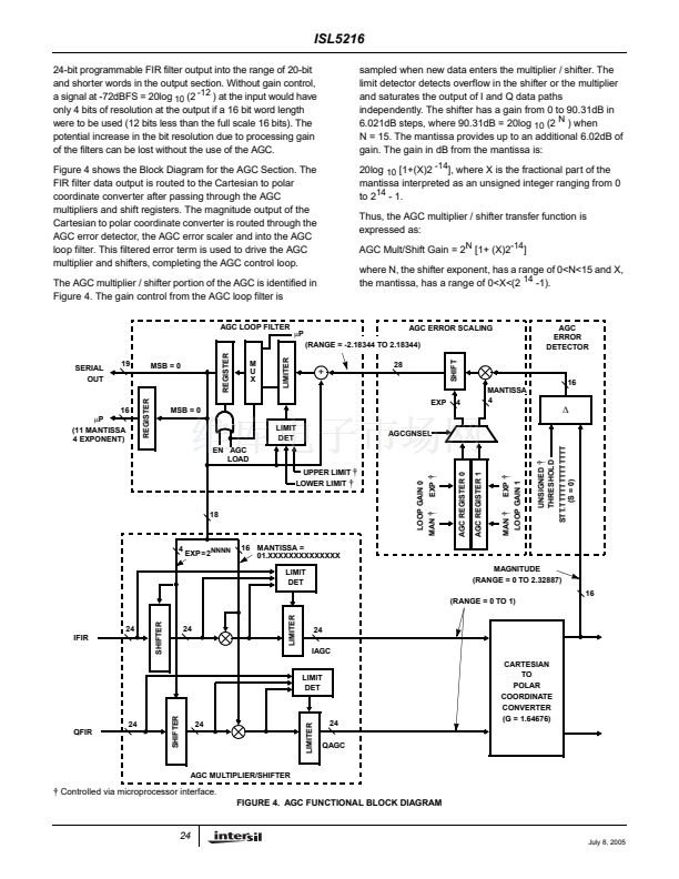
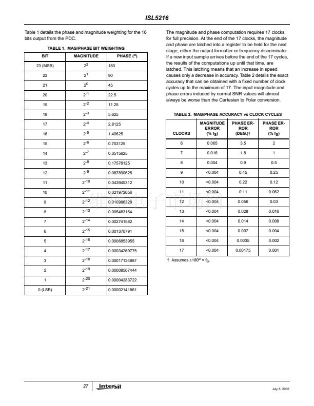
ISL5216
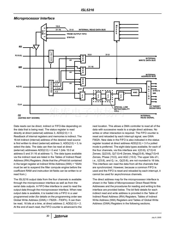
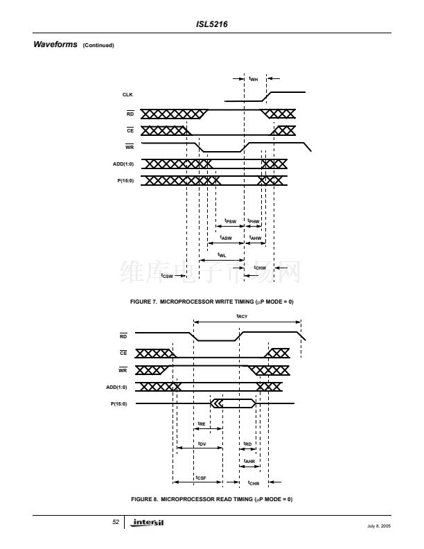
15-BIT MODE: 15-BIT MANTISSA (15:1), 2-BIT EXPONENT (-1, 0), 18dB MAXIMUM EXPONENT RANGE (Note 12)
EXPONENT
000
001
010
011
NOTE:
12. To select this mode, set IWA *000H / GWA F804H bits 17, 16, 8 and 7 to 1, 1, 0 and 0 respectively.
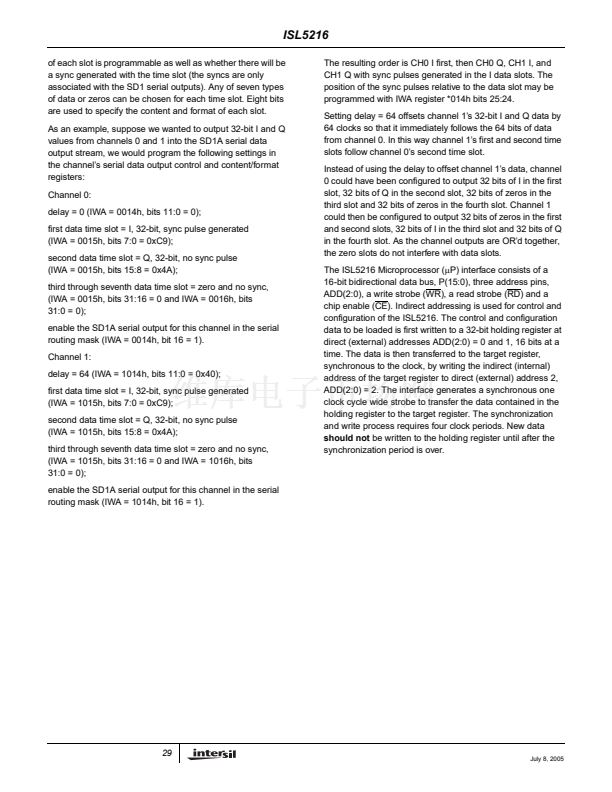
16-BIT MODE: 16-BIT MANTISSA (15:0), 1-BIT EXPONENT (-1), 6dB MAXIMUM EXPONENT RANGE (Note 13)
EXPONENT
X(-1) = 0
X(-1) = 1
NOTE:
13. To select this mode, set IWA *000H / GWA F804H bits 17, 16, 8 and 7 to 1, 1, 0 and 1 respectively.
0
6
GAIN (dB)
X15
X15
X14
X14
X13
X13
PIN BIT WEIGHTING TO 16-BIT INPUT MAPPING
X12
X12
X11
X11
X10
X10
X9
X9
X8
X8
X7
X7
X6
X6
X5
X5
X4
X4
X3
X3
X2
X2
X1
X1
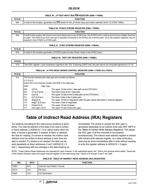
X0
X0
0
6
12
18
GAIN (dB)
X15
X15
X15
X15
X14
X14
X14
X14
X13
X13
X13
X13
PIN BIT WEIGHTING TO 16-BIT INPUT MAPPING
X12
X12
X12
X12
X11
X11
X11
X11
X10
X10
X10
X10
X9
X9
X9
X9
X8
X8
X8
X8
X7
X7
X7
X7
X6
X6
X6
X6
X5
X5
X5
X5
X4
X4
X4
X4
X3
X3
X3
X3
X2
X2
X2
X2
X1
X1
X1
X1
0
0
0
0
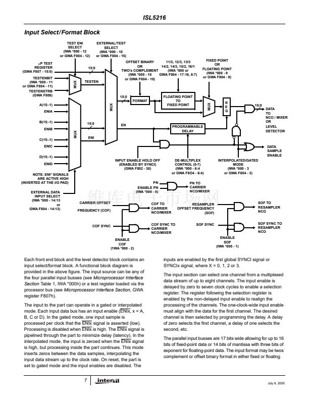
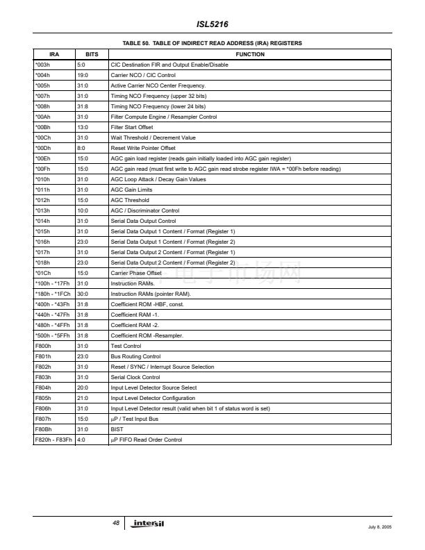
Level Detector
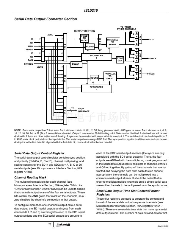
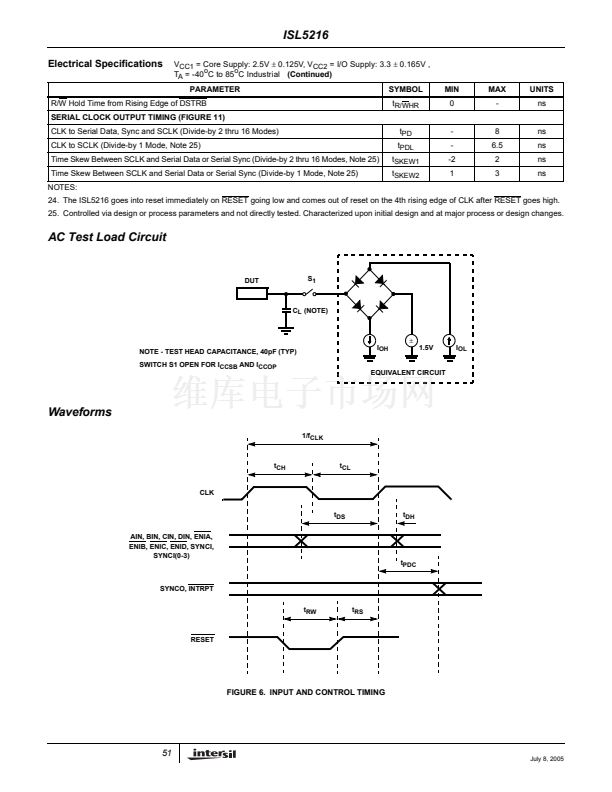
An input level detector is provided to monitor the signal level
on any of the input busses. The input bus, input format, and
the level detection type are programmable (see
Microprocessor Interface
section, GWA registers F804h,
F805h and F806h). This signal level represents the wideband
signal from the A/D and is useful for controlling gain /
attenuation blocks ahead of the converter.
The supported monitoring modes are: integrated magnitude
(like the HSP50214 w/o the threshold), leaky integration
(Y
n
= X
n
x A + Y
n-1
x (1-A)) where A = 1, 2
-8
, 2
-12
, or 2
-16
(see GWA = F805h), and peak detection. The measurement
interval can be programmed from 2 to 65537 samples (or
continuous for the leaky integrator and peak detect cases).
The output is 32 bits and is read via the
碌P
interface.
Note that the accumulators in the input level detector are 32
bits wide. This may limit the integration range to as few as
512 samples (for a 42dB exponent range).
EN
BARREL SHIFTER
A
A>B
危
16
B
EN
R
E
G
2
0, -8, -12, -16
32
FIGURE 2. PEAK DETECTOR
Y
N
= A * X + (1 - A) * Y
N-1
BARREL SHIFTER
16
X
危
R
E
G
Y
32
BARREL SHIFTER
MSB
16
ACCUMULATOR
32
A=2
2
0, -8, -12, -16
0, -8, -12, -16
FIGURE 3. LEAKY INTEGRATOR
FIGURE 1. INTEGRATED MODE
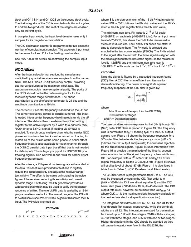
Complex Input Mode
In this mode, complex (I/Q) data can be input using two clock
cycles with I input first and Q input second. The ENIx signal
indicates the clock cycle when I is valid. The Q data is taken
on either the next input clock or two clocks after I, as
determined by IWA *000H bit 23. The complex multiply is
done in two clock cycles: I * COS and I * SIN on the first
10
BARREL SHIFTER
ABSOLUTE
VALUE
July 8, 2005


 1
1
 2
2
 3
3
 4
4
 5
5
 6
6
 7
7
 8
8
 9
9
 10
10
 11
11
 12
12
 13
13
 14
14
 15
15
 16
16
 17
17
 18
18
 19
19
 20
20
 21
21
 22
22
 23
23
 24
24
 25
25
 26
26
 27
27
 28
28
 29
29
 30
30
 31
31
 32
32
 33
33
 34
34
 35
35
 36
36
 37
37
 38
38
 39
39
 40
40
 41
41
 42
42
 43
43
 44
44
 45
45
 46
46
 47
47
 48
48
 49
49
 50
50
 51
51
 52
52
 53
53
 54
54
 55
55
 56
56
 57
57
 58
58
 59
59
 60
60
 61
61
 62
62
 63
63
 64
64
 65
65
