/2. f
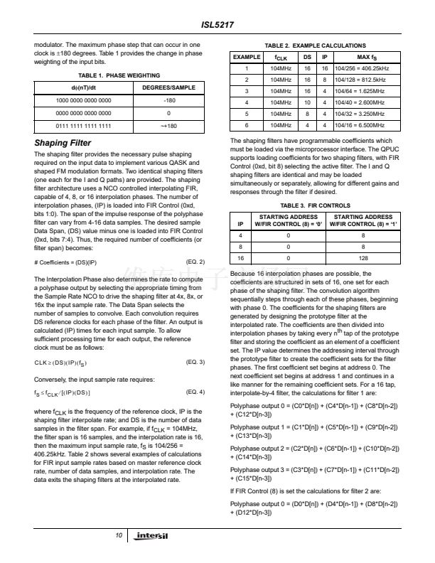
is the CLK frequency.
This NCO frequency range allows for spectral inversion.
鈦?/div>
f
CLK
*2
32
]
(EQ. 6)
-80
where INT[X] is the integer part of the real number X.
-100
-120
64
128
192
256
320
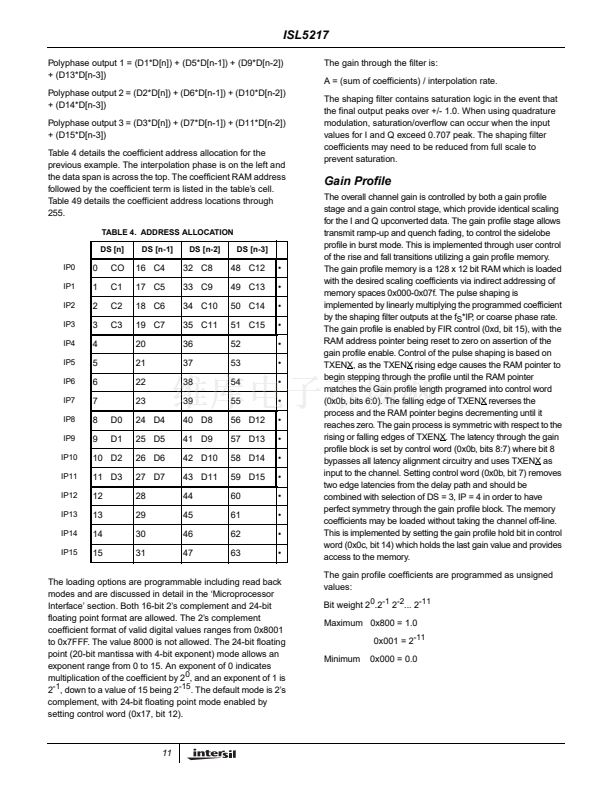
SAMPLE TIMES
384
448
512
FIGURE 13B. INTERPOLATION FILTER IMPULSE RESPONSE
L = 16; FOUT = 4096
0
-0.05
-0.1
-0.15
MAGNITUDE (dB)
-0.2
-0.25
-0.3
-0.35
-0.4
-0.45
-0.5
-0.55
-0.6
-0.65
-0.7
8
16
24
32
40
48
56
64
The vector rotation can also be controlled by the sign of the
CF value. When CF is a positive value a counterclockwise
vector rotation is produced. When CF is a negative value a
clockwise vector rotation is produced.
The carrier frequency is loaded 16 bits at a time into Control
Words 8 and 9.
0x8, bits 15:0 = CF (31:16)
0x9, bits 15:0 = CF (15:0)
The 16-bit carrier phase offset initializes the most-significant
16-bits of the phase accumulator. The least significant 16
bits of the phase accumulator are cleared. Given a desired
carrier phase offset, the value CO(31:0) can be calculated by
the following equation.
(
PhaseOffset
)擄
32
-
CO
(
31:0
)
=
INT
--------------------------------------------
*2
]
360擄
(EQ. 7)
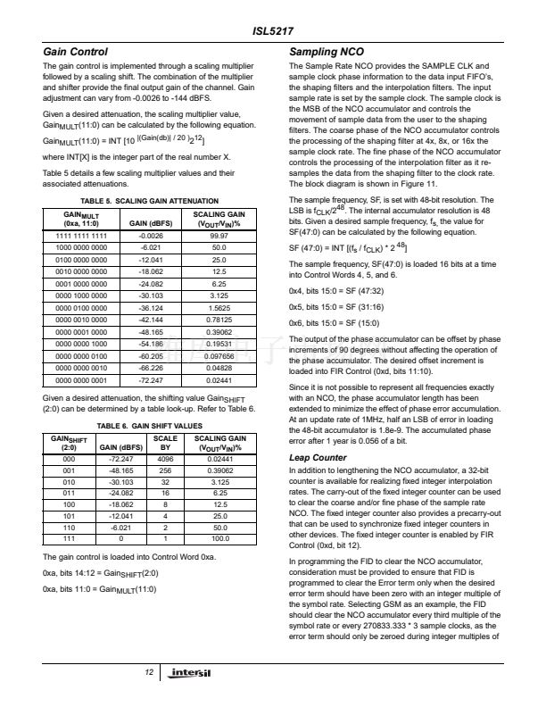
INTERPOLATION FILTER RESPONSE
The carrier phase offset is loaded into Control Word 0x7.
Control Word 7 (15:0) = CO (31:16).
SAMPLE TIMES
FIGURE 13C. INTERPOLATION FILTER IMPULSE RESPONSE
L = 16; FOUT = 4096
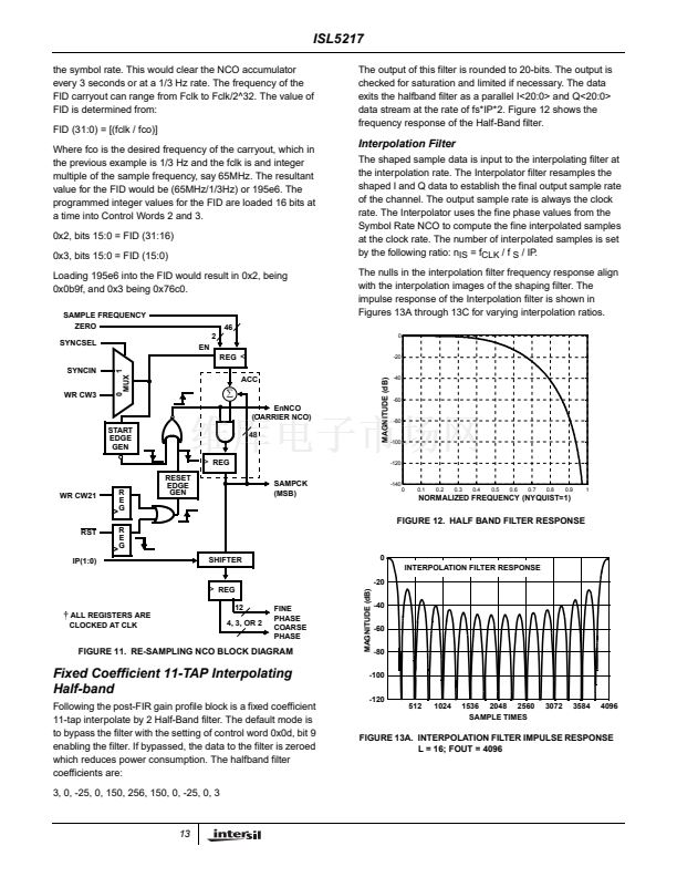
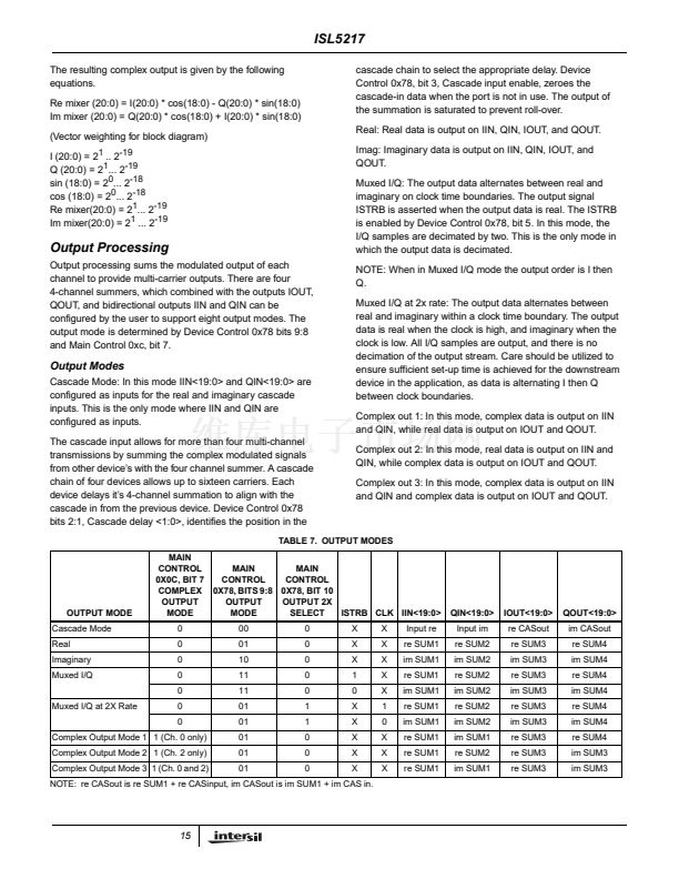
Complex Mixer
The complex mixer multiplies the sin/cos terms generated by
the carrier NCO sin/cos generator with the I and Q
interpolated sample data. The mixers can be bypassed by
programming the carrier frequency to zero. This action sets
the sin/cos terms generated by the carrier NCO to 0 and 1
respectively. The block diagram of the Carrier NCO/Complex
Mixer is shown in Figure 14.
I(20:0)
COS
SIN
Q(20:0)
EN OUT
Q(20:0)
COS
SIN
I(20:0)
EN OUT
19
19
19
19
Carrier NCO
Following the interpolating filter section, the samples are
modulated onto a carrier signal via a complex multiply
operation. The Carrier NCO provides the quadrature local
oscillator references to the complex mixer.
The NCO has provisions for programming the frequency and
phase offset. The NCO has a 32 bit frequency control
providing sub-hertz resolution at the maximum clock rate.
The carrier NCO phase accumulator feedback can be preset
to synchronize multiple channels. The carrier NCO has a
32-bit 2鈥檚 complement programmable frequency increment
value which can range from -2
31
to ~2
31
for a NCO output
range of -f
CLK
/2 to
~
f
CLK
/2. For f
CLK
= 104MHz, the
frequency will range from -52MHz to +52MHz.
The maximum error is 104MHz/(2
32
) = 0.0242Hz. The
carrier frequency can be calculated from the value loaded
into Control Address 0x8 and 0x9 by:
F
CARRIER
=
CR
(
31:0
) 脳
f
CLK
脳
2
鈥?/div>
32
鈭?/div>
+
-
Re (20:0)
鈭?/div>
+
+
Im (20:0)
(EQ. 5)
FIGURE 14. VECTOR MODULATOR/MIXER BLOCK DIAGRAM
14


 1
1
 2
2
 3
3
 4
4
 5
5
 6
6
 7
7
 8
8
 9
9
 10
10
 11
11
 12
12
 13
13
 14
14
 15
15
 16
16
 17
17
 18
18
 19
19
 20
20
 21
21
 22
22
 23
23
 24
24
 25
25
 26
26
 27
27
 28
28
 29
29
 30
30
 31
31
 32
32
 33
33
 34
34
 35
35
 36
36
 37
37
 38
38
 39
39
 40
40
 41
41
 42
42
 43
43
