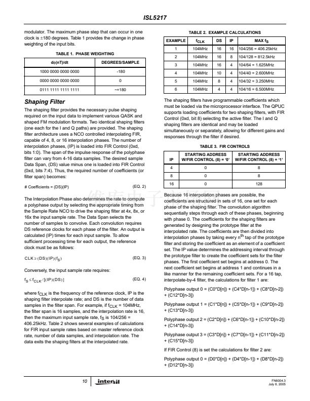
A1 CORNER I.D.
Rev. 1 12/00
CORNER I.D.
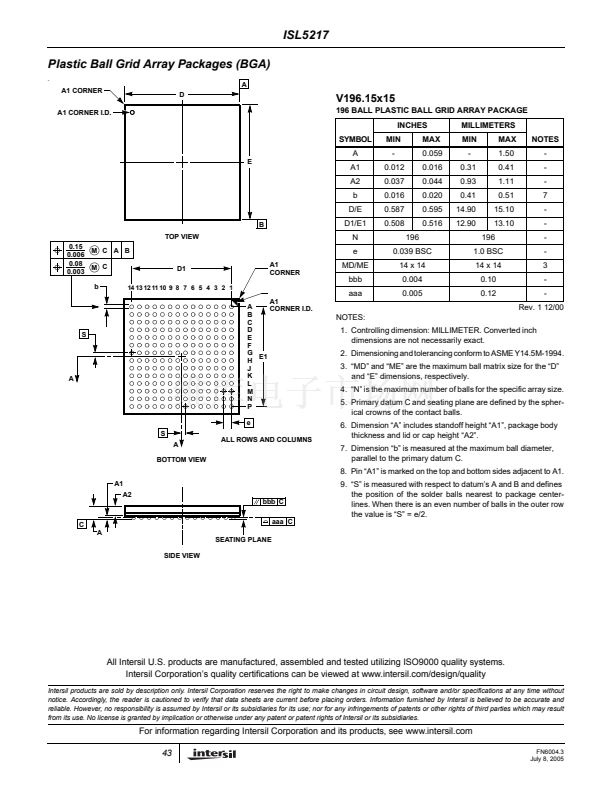
1. Controlling dimension: MILLIMETER. Converted inch
dimensions are not necessarily exact.
2. Dimensioning and tolerancing conform to ASME Y14.5M-1994.
3. 鈥淢D鈥?and 鈥淢E鈥?are the maximum ball matrix size for the 鈥淒鈥?/div>
and 鈥淓鈥?dimensions, respectively.
4. 鈥淣鈥?is the maximum number of balls for the specific array size.
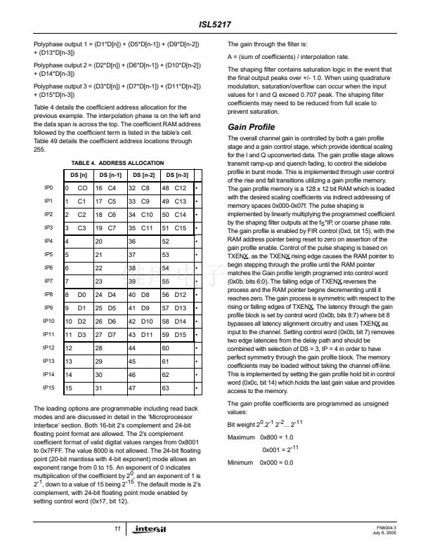
5. Primary datum C and seating plane are defined by the spher-
ical crowns of the contact balls.
6. Dimension 鈥淎鈥?includes standoff height 鈥淎1鈥? package body
thickness and lid or cap height 鈥淎2鈥?
7. Dimension 鈥渂鈥?is measured at the maximum ball diameter,
parallel to the primary datum C.
8. Pin 鈥淎1鈥?is marked on the top and bottom sides adjacent to A1.
9. 鈥淪鈥?is measured with respect to datum鈥檚 A and B and defines
the position of the solder balls nearest to package center-
lines. When there is an even number of balls in the outer row
the value is 鈥淪鈥?= e/2.
S
A
S
A
BOTTOM VIEW
ALL ROWS AND COLUMNS
A1
A2
bbb C
C
A
SEATING PLANE
SIDE VIEW
aaa C
All Intersil U.S. products are manufactured, assembled and tested utilizing ISO9000 quality systems.
Intersil Corporation鈥檚 quality certifications can be viewed at www.intersil.com/design/quality
Intersil products are sold by description only. Intersil Corporation reserves the right to make changes in circuit design, software and/or specifications at any time without
notice. Accordingly, the reader is cautioned to verify that data sheets are current before placing orders. Information furnished by Intersil is believed to be accurate and
reliable. However, no responsibility is assumed by Intersil or its subsidiaries for its use; nor for any infringements of patents or other rights of third parties which may result
from its use. No license is granted by implication or otherwise under any patent or patent rights of Intersil or its subsidiaries.
For information regarding Intersil Corporation and its products, see www.intersil.com
43
FN6004.3
July 8, 2005


 1
1
 2
2
 3
3
 4
4
 5
5
 6
6
 7
7
 8
8
 9
9
 10
10
 11
11
 12
12
 13
13
 14
14
 15
15
 16
16
 17
17
 18
18
 19
19
 20
20
 21
21
 22
22
 23
23
 24
24
 25
25
 26
26
 27
27
 28
28
 29
29
 30
30
 31
31
 32
32
 33
33
 34
34
 35
35
 36
36
 37
37
 38
38
 39
39
 40
40
 41
41
 42
42
 43
43
