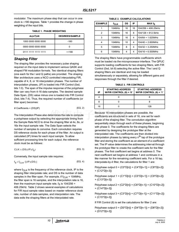
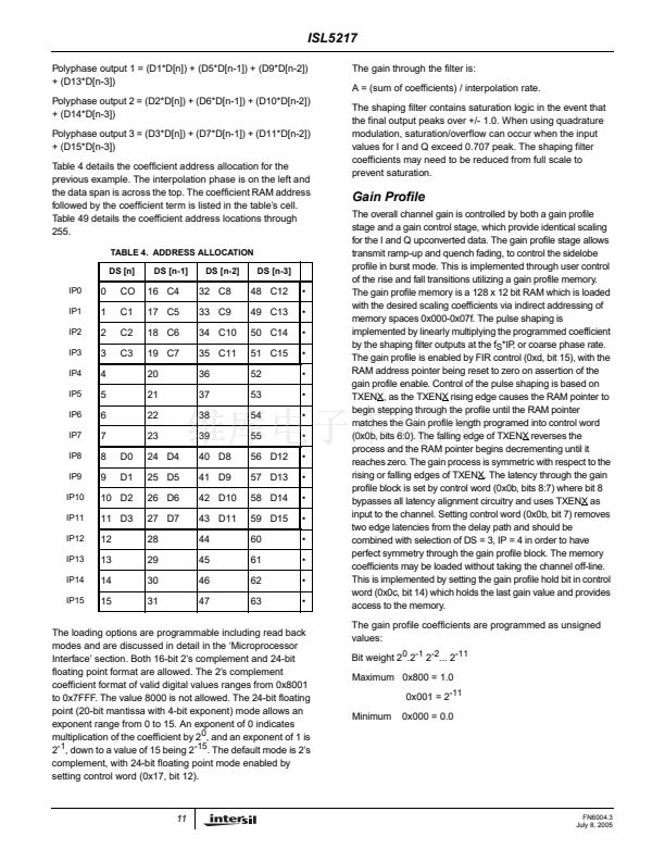
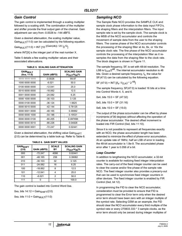
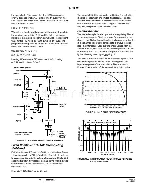
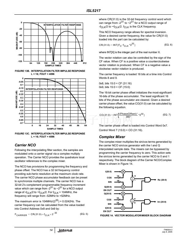
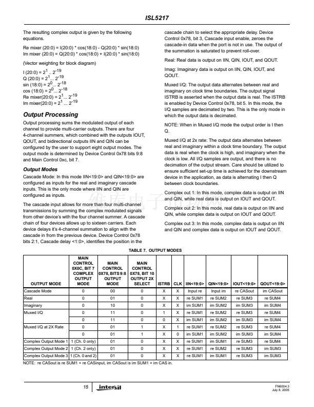
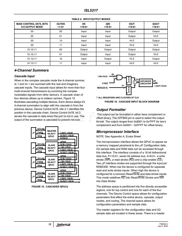
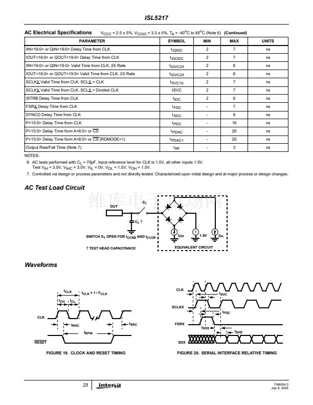
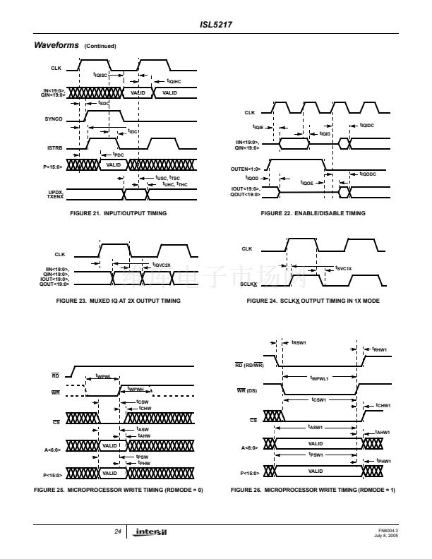
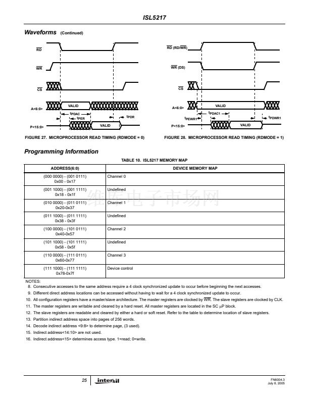
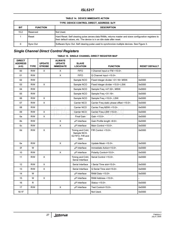
ISL5217
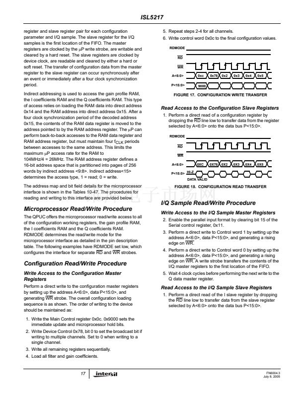
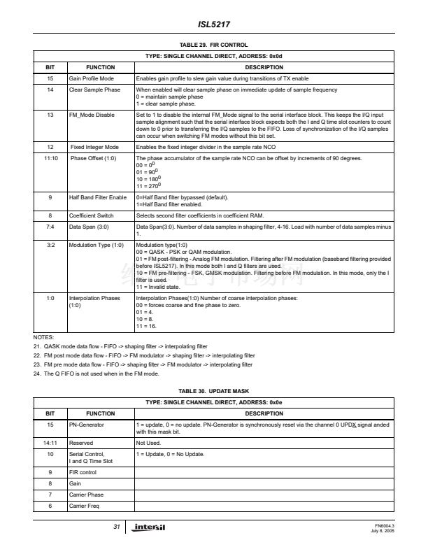
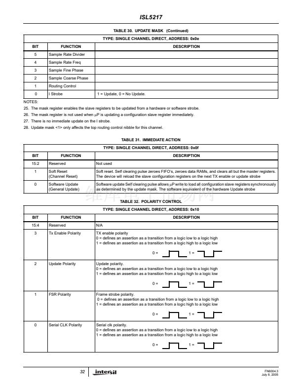
TABLE 33. SERIAL CONTROL (13:0)
TYPE: SINGLE CHANNEL DIRECT, ADDRESS: 0x11
BIT
15
FUNCTION
Serial/parallel Data
Select
Epoch Frame Strobe
Enable
DESCRIPTION
Selects the source of the symbol data for input.
0 =
碌P
port, (parallel interface)
1 = serial port, (one of four serial ports)
Selects a pre-carry out of the fixed integer divider instead of the serial frame strobe. The pre-carry out is
six clocks ahead of the true carry out. This strobe is used to synchronize fixed integer dividers on other
devices.
0 = serial frame strobe.
1 = epoch frame strobe.
Clock divider to generate 1 of 16 serial clock rates
0000 = clk/2
1101 = clk/28
0001 = clk/4
1110 = clk/30
0010 = clk/6
1111 = clk/32
Selects the source for serial TX clock output.
00 = Disables serial clock divider and serial clock out.
01 = Select 1x clock rate.
10 = Select divided clock rate.
11 = Select 32x sample clock rate.
Selects the TX enable port. The rising edge flushes data, (16 clks) and updates configuration slave
registers as determined by the update mask. High level allows serial requests to occur. Low level inhibits
additional serial data requests, (assertion of TX frame strobe).
00 = TX enable A.
01 = TX enable B.
10 = TX enable C.
11 = TX enable D.
Selects the Update port. The Update strobe is used to update all slave configuration registers as
determined by the update mask.
00 = Update A.
01 = Update B.
10 = Update C.
11 = Update D.
Selects the word length of the incoming serial data The value is for one data word and is the same for
both I and Q data.
00 = 16 bits.
01 = 12 bits.
10 = 8 bits.
11 = 4 bits.
14
13:10
Serial Clock Rate (3:0)
9:8
Serial Clock Mode (1:0)
7:6
Select TX Enable (1:0)
5:4
Select Update(1:0)
3:2
Serial Word Length (1:0)
1:0
Select Serial Data in (1:0) Selects the serial data in port.
00 = Serial data A.
01 = Serial data B.
10 = Serial data C.
11 = Serial data D.
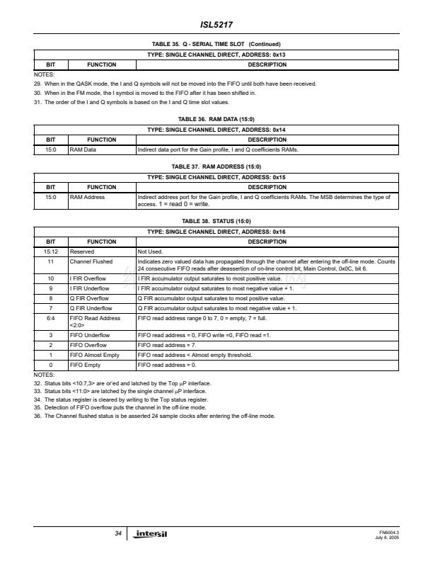
TABLE 34. I - SERIAL TIME SLOT
TYPE: SINGLE CHANNEL DIRECT, ADDRESS: 0x12
BIT
15:10
9:0
FUNCTION
Reserved
I Time Slot(9:0)
Not Used.
DESCRIPTION
The
I - SERIAL TIME SLOT
is a 10 bit counter clocked at the serial clock rate. The counter begins on
assertion of the Frame strobe. The carryout determines when a valid I symbol has been shifted in.
TABLE 35. Q - SERIAL TIME SLOT
TYPE: SINGLE CHANNEL DIRECT, ADDRESS: 0x13
BIT
15:10
9:0
FUNCTION
Reserved
Q Time Slot (9:0)
Not Used.
DESCRIPTION
The
Q - SERIAL TIME SLOT
is a 10 bit counter clocked at the serial clock rate. The counter begins on
assertion of the Frame strobe. The carryout determines when a valid Q symbol has been shifted in.
33
FN6004.3
July 8, 2005


 1
1
 2
2
 3
3
 4
4
 5
5
 6
6
 7
7
 8
8
 9
9
 10
10
 11
11
 12
12
 13
13
 14
14
 15
15
 16
16
 17
17
 18
18
 19
19
 20
20
 21
21
 22
22
 23
23
 24
24
 25
25
 26
26
 27
27
 28
28
 29
29
 30
30
 31
31
 32
32
 33
33
 34
34
 35
35
 36
36
 37
37
 38
38
 39
39
 40
40
 41
41
 42
42
 43
43
