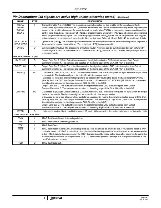
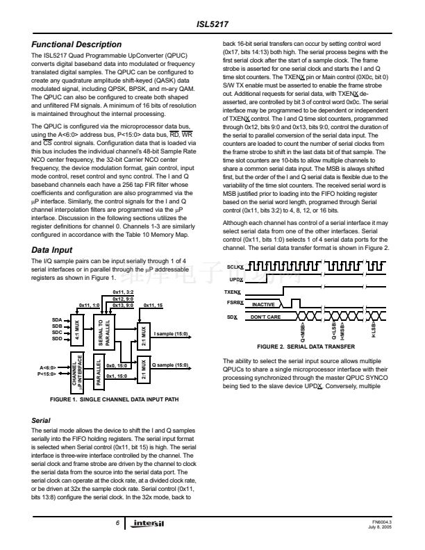
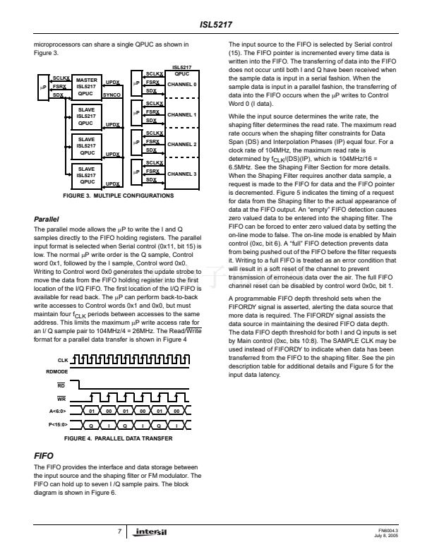
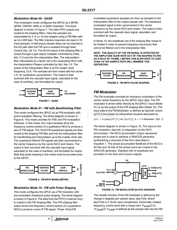
鈦?/div>
[
(
IP
) (
DS
) ]
(EQ. 4)
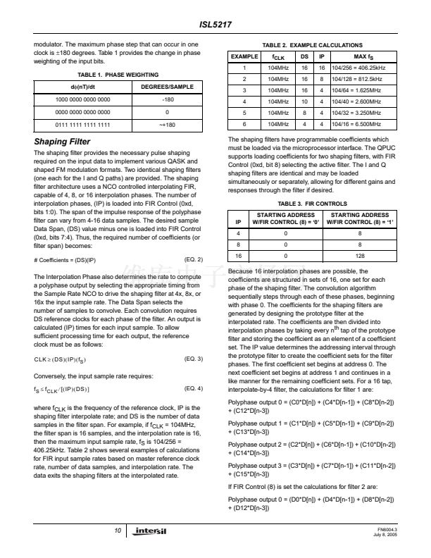
Because 16 interpolation phases are possible, the
coefficients are structured in sets of 16, one set for each
phase of the shaping filter. The convolution algorithm
sequentially steps through each of these phases, beginning
with phase 0. The coefficients for the shaping filters are
generated by designing the prototype filter at the
interpolated rate. The coefficients are then divided into
interpolation phases by taking every n
th
tap of the prototype
filter and storing the coefficient as an element of a coefficient
set. The IP value determines the addressing interval through
the prototype filter to create the coefficient sets for the filter
phases. The first coefficient set begins at address 0. The
next coefficient set begins at address 1 and continues in a
like manner for the remaining coefficient sets. For a 16 tap,
interpolate-by-4 filter, the calculations for filter 1 are:
Polyphase output 0 = (C0*D[n]) + (C4*D[n-1]) + (C8*D[n-2])
+ (C12*D[n-3])
Polyphase output 1 = (C1*D[n]) + (C5*D[n-1]) + (C9*D[n-2])
+ (C13*D[n-3])
Polyphase output 2 = (C2*D[n]) + (C6*D[n-1]) + (C10*D[n-2])
+ (C14*D[n-3])
Polyphase output 3 = (C3*D[n]) + (C7*D[n-1]) + (C11*D[n-2])
+ (C15*D[n-3])
If FIR Control (8) is set the calculations for filter 2 are:
Polyphase output 0 = (D0*D[n]) + (D4*D[n-1]) + (D8*D[n-2])
+ (D12*D[n-3])
where f
CLK
is the frequency of the reference clock, IP is the
shaping filter interpolate rate; and DS is the number of data
samples in the filter span. For example, if f
CLK
= 104MHz,
the filter span is 16 samples, and the interpolation rate is 16,
then the maximum input sample rate, f
S
is 104/256 =
406.25kHz. Table 2 shows several examples of calculations
for FIR input sample rates based on master reference clock
rate, number of data samples, and interpolation rate. The
data exits the shaping filters at the interpolated rate.
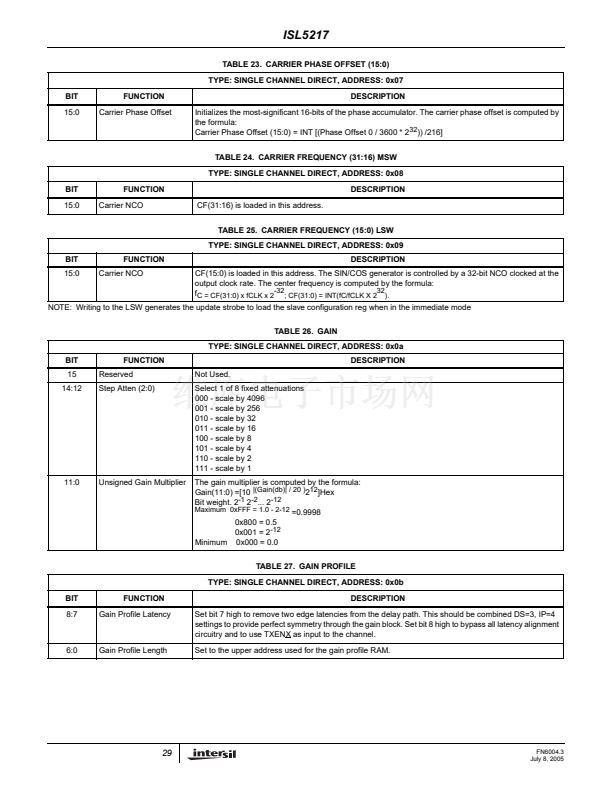
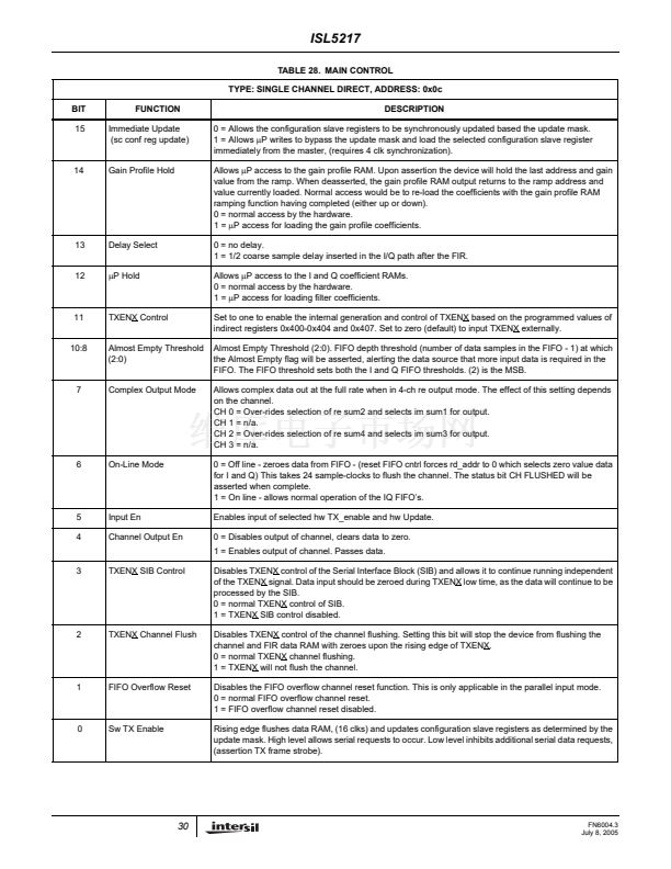
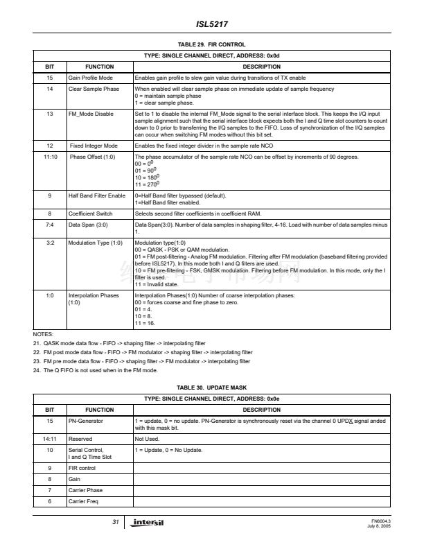
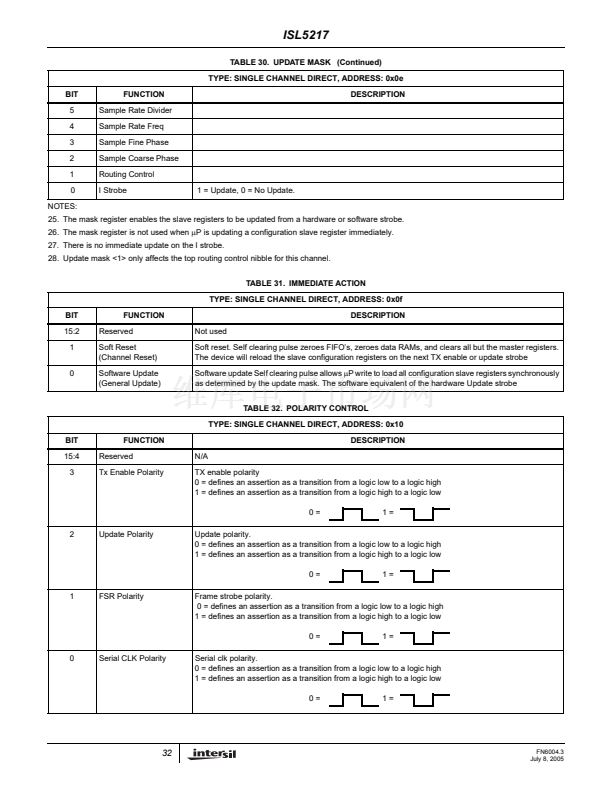
10
FN6004.3
July 8, 2005


 1
1
 2
2
 3
3
 4
4
 5
5
 6
6
 7
7
 8
8
 9
9
 10
10
 11
11
 12
12
 13
13
 14
14
 15
15
 16
16
 17
17
 18
18
 19
19
 20
20
 21
21
 22
22
 23
23
 24
24
 25
25
 26
26
 27
27
 28
28
 29
29
 30
30
 31
31
 32
32
 33
33
 34
34
 35
35
 36
36
 37
37
 38
38
 39
39
 40
40
 41
41
 42
42
 43
43
