ISL5216
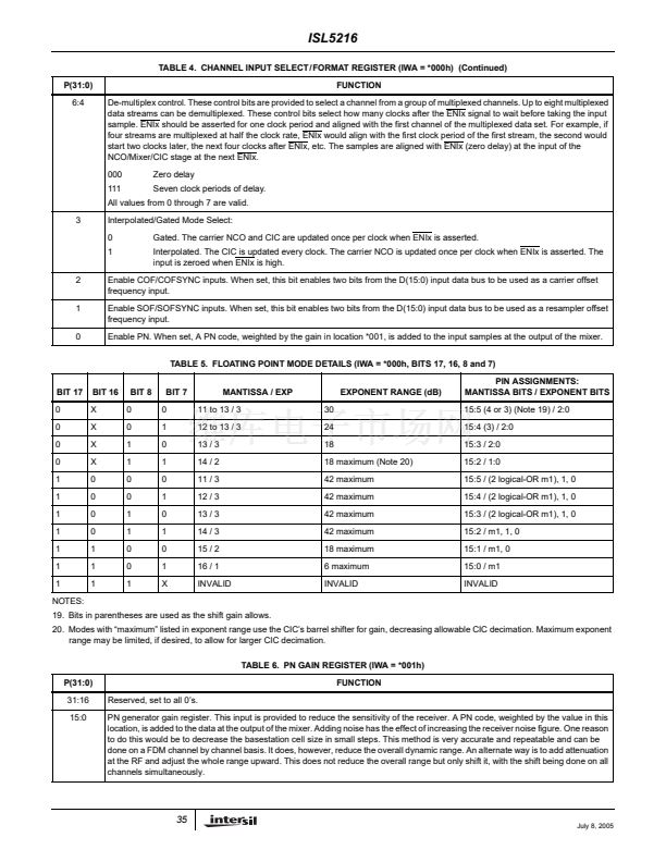
point modes. The floating point modes and the mapping of the
parallel 17-bit input format is discussed below.
mode as well as those which follow it in the tables below use
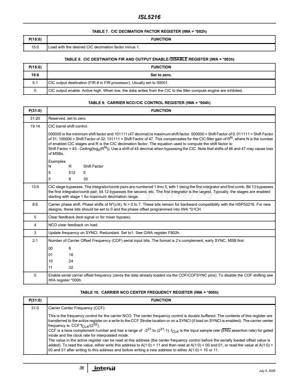
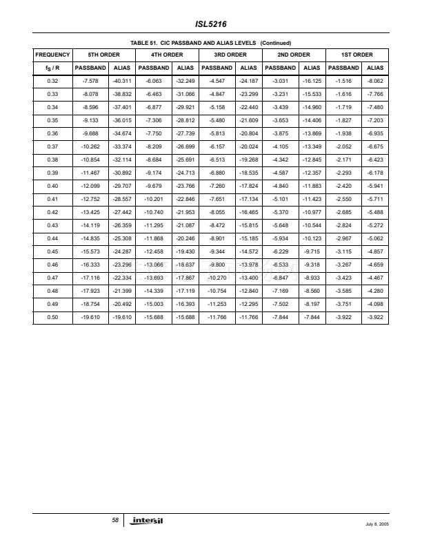
the CIC鈥檚 barrel shifter to provide the gain. This places a limit
on the CIC鈥檚 largest available decimation. As an example,
assume the CIC is set for 5th order and the decimation
needs to be 300. The CIC鈥檚 gain, 300
5
, is compensated for
in the barrel shifter with a shift factor of 45 - ceil(log
2
(300
5
)) =
3 where shifts are from LSB towards MSB and a shift of 45
corresponds to no attenuation. If the shift factor is set as 0 in
this example, there is room for 3 * 6 = 18dB of gain. Raising
the CIC decimation lowers the shift factor (to further
attenuate the CIC input signal) and limits the available gain
range. This CIC decimation / floating point gain range trade
off is handled automatically by the evaluation board
software. Additional information on the CIC can be found in
the CIC Filter section of this data sheet.
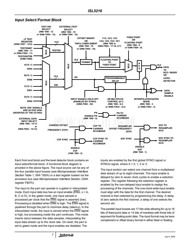
Floating Point Input Mode Bit Mapping
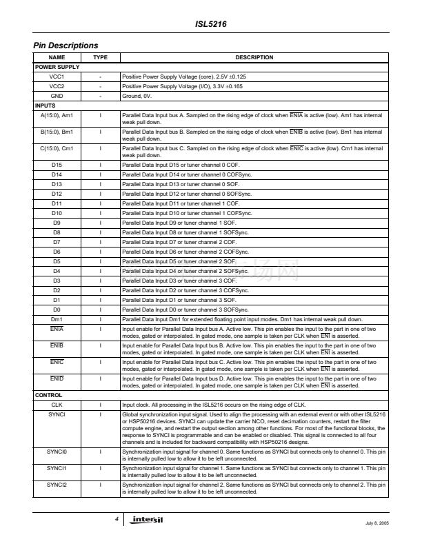
The input bit weighting for fixed point inputs on busses A, B,
C, and D is:
bit 15 (MSB): 2
0
, bit 14: 2
-1
, bit 13: 2
-2
, ..., bit 0: 2
-15
.
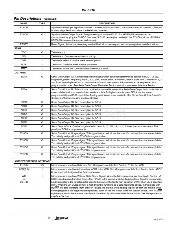
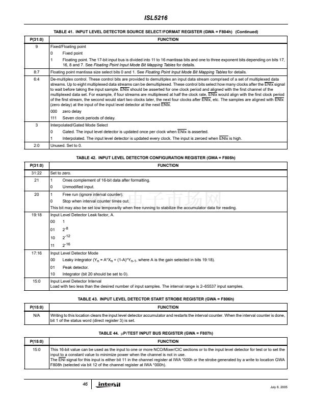
For floating point modes, the least significant two or three
bits are used as exponent bits (See
Floating Point Input
Mode Bit Mapping Tables).
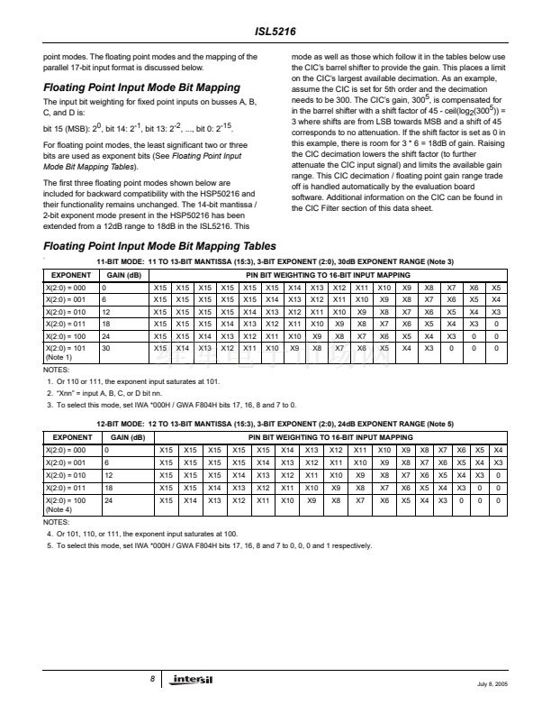
The first three floating point modes shown below are
included for backward compatibility with the HSP50216 and
their functionality remains unchanged. The 14-bit mantissa /
2-bit exponent mode present in the HSP50216 has been
extended from a 12dB range to 18dB in the ISL5216. This
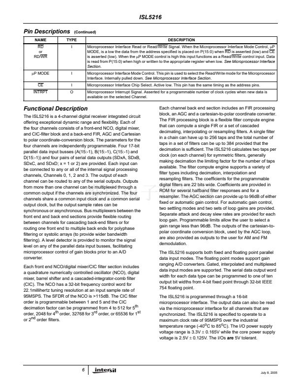
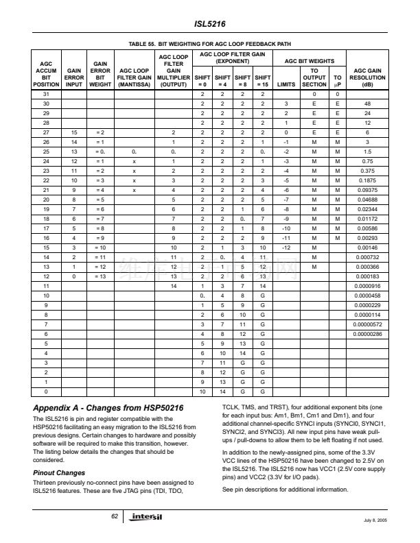
Floating Point Input Mode Bit Mapping Tables
((
11-BIT MODE: 11 TO 13-BIT MANTISSA (15:3), 3-BIT EXPONENT (2:0), 30dB EXPONENT RANGE (Note 3)
EXPONENT
X(2:0) = 000
X(2:0) = 001
X(2:0) = 010
X(2:0) = 011
X(2:0) = 100
X(2:0) = 101
(Note 1)
0
6
12
18
24
30
GAIN (dB)
X15
X15
X15
X15
X15
X15
X15
X15
X15
X15
X15
X14
X15
X15
X15
X15
X14
X13
X15
X15
X15
X14
X13
X12
PIN BIT WEIGHTING TO 16-BIT INPUT MAPPING
X15
X15
X14
X13
X12
X11
X15
X14
X13
X12
X11
X10
X14
X13
X12
X11
X10
X9
X13
X12
X11
X10
X9
X8
X12
X11
X10
X9
X8
X7
X11
X10
X9
X8
X7
X6
X10
X9
X8
X7
X6
X5
X9
X8
X7
X6
X5
X4
X8
X7
X6
X5
X4
X3
X7
X6
X5
X4
X3
0
X6
X5
X4
X3
0
0
X5
X4
X3
0
0
0
NOTES:
1. Or 110 or 111, the exponent input saturates at 101.
2. 鈥淴nn鈥?= input A, B, C, or D bit nn.
3. To select this mode, set IWA *000H / GWA F804H bits 17, 16, 8 and 7 to 0.
12-BIT MODE: 12 TO 13-BIT MANTISSA (15:3), 3-BIT EXPONENT (2:0), 24dB EXPONENT RANGE (Note 5)
EXPONENT
X(2:0) = 000
X(2:0) = 001
X(2:0) = 010
X(2:0) = 011
X(2:0) = 100
(Note 4)
NOTES:
4. Or 101, 110, or 111, the exponent input saturates at 100.
5. To select this mode, set IWA *000H / GWA F804H bits 17, 16, 8 and 7 to 0, 0, 0 and 1 respectively.
0
6
12
18
24
GAIN (dB)
X15
X15
X15
X15
X15
X15
X15
X15
X15
X14
X15
X15
X15
X14
X13
X15
X15
X14
X13
X12
PIN BIT WEIGHTING TO 16-BIT INPUT MAPPING
X15
X14
X13
X12
X11
X14
X13
X12
X11
X10
X13
X12
X11
X10
X9
X12
X11
X10
X9
X8
X11
X10
X9
X8
X7
X10
X9
X8
X7
X6
X9
X8
X7
X6
X5
X8
X7
X6
X5
X4
X7
X6
X5
X4
X3
X6
X5
X4
X3
0
X5
X4
X3
0
0
X4
X3
0
0
0
8
July 8, 2005


 1
1
 2
2
 3
3
 4
4
 5
5
 6
6
 7
7
 8
8
 9
9
 10
10
 11
11
 12
12
 13
13
 14
14
 15
15
 16
16
 17
17
 18
18
 19
19
 20
20
 21
21
 22
22
 23
23
 24
24
 25
25
 26
26
 27
27
 28
28
 29
29
 30
30
 31
31
 32
32
 33
33
 34
34
 35
35
 36
36
 37
37
 38
38
 39
39
 40
40
 41
41
 42
42
 43
43
 44
44
 45
45
 46
46
 47
47
 48
48
 49
49
 50
50
 51
51
 52
52
 53
53
 54
54
 55
55
 56
56
 57
57
 58
58
 59
59
 60
60
 61
61
 62
62
 63
63
 64
64
 65
65
