A1 CORNER I.D.
Rev. 2 12/00
CORNER I.D.
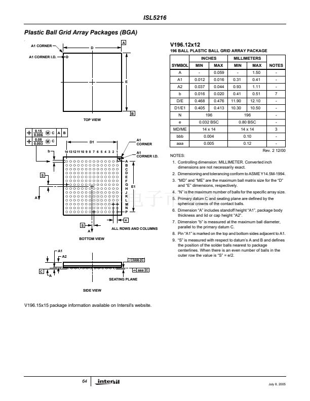
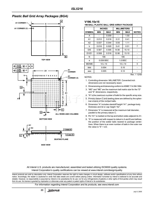
1. Controlling dimension: MILLIMETER. Converted inch
dimensions are not necessarily exact.
2. Dimensioning and tolerancing conform to ASME Y14.5M-1994.
3. 鈥淢D鈥?and 鈥淢E鈥?are the maximum ball matrix size for the 鈥淒鈥?/div>
and 鈥淓鈥?dimensions, respectively.
4. 鈥淣鈥?is the maximum number of balls for the specific array size.
5. Primary datum C and seating plane are defined by the
spherical crowns of the contact balls.
6. Dimension 鈥淎鈥?includes standoff height 鈥淎1鈥? package body
thickness and lid or cap height 鈥淎2鈥?
7. Dimension 鈥渂鈥?is measured at the maximum ball diameter,
parallel to the primary datum C.
8. Pin 鈥淎1鈥?is marked on the top and bottom sides adjacent to A1.
9. 鈥淪鈥?is measured with respect to datum鈥檚 A and B and defines
the position of the solder balls nearest to package
centerlines. When there is an even number of balls in the
outer row the value is 鈥淪鈥?= e/2.
S
A
S
A
BOTTOM VIEW
ALL ROWS AND COLUMNS
A1
A2
bbb C
C
A
SEATING PLANE
SIDE VIEW
aaa C
V196.15x15 package information available on Intersil鈥檚 website.
V
64
July 8, 2005


 1
1
 2
2
 3
3
 4
4
 5
5
 6
6
 7
7
 8
8
 9
9
 10
10
 11
11
 12
12
 13
13
 14
14
 15
15
 16
16
 17
17
 18
18
 19
19
 20
20
 21
21
 22
22
 23
23
 24
24
 25
25
 26
26
 27
27
 28
28
 29
29
 30
30
 31
31
 32
32
 33
33
 34
34
 35
35
 36
36
 37
37
 38
38
 39
39
 40
40
 41
41
 42
42
 43
43
 44
44
 45
45
 46
46
 47
47
 48
48
 49
49
 50
50
 51
51
 52
52
 53
53
 54
54
 55
55
 56
56
 57
57
 58
58
 59
59
 60
60
 61
61
 62
62
 63
63
 64
64
 65
65
