ISL5216
Absolute Maximum Ratings
Supply Voltage . . . . . . . . . . . . . . . . . . . . . . . . . . . . . . . . . . . . . . 4.6V
Core Supply Voltage . . . . . . . . . . . . . . . . . . . . . . . . . . . . . . . . . 3.5V
Input, Output or I/O Voltage . . . . . . . . . . . . GND -0.5V to V
CC
+0.5V
ESD Classification . . . . . . . . . . . . . . . . . . . . . . . . . . . . . . . . . Class I
Thermal Information
Thermal Resistance (Typical)
胃
JA
(
o
C/W)
Operating Conditions
Voltage Range (I/O) . . . . . . . . . . . . . . . . . . . . . . +3.135V to +3.465V
Voltage Range (core) . . . . . . . . . . . . . . . . . . . . .+2.375V to +2.625V
Temperature Range
Industrial. . . . . . . . . . . . . . . . . . . . . . . . . . . . . . . . -40
o
C to +85
o
C
Input Low Voltage . . . . . . . . . . . . . . . . . . . . . . . . . . . . . 0V to +0.8V
Input High Voltage . . . . . . . . . . . . . . . . . . . . . . . . . . . .2V to I/O V
CC
196 Lead BGA Package (0.8 mm pitch). . . . . . . . . .
30
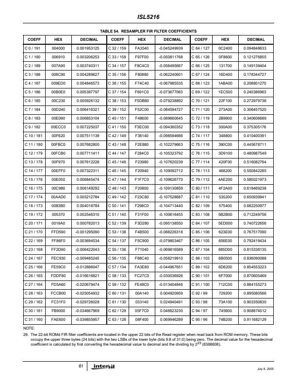
w/200 LFM Air Flow . . . . . . . . . . . . . . . . . . . . . . . . .
27
w/400 LFM Air Flow . . . . . . . . . . . . . . . . . . . . . . . . .
26
196 Lead BGA Package (1.0 mm pitch). . . . . . . . . .
29
w/200 LFM Air Flow . . . . . . . . . . . . . . . . . . . . . . . . .
26
w/400 LFM Air Flow . . . . . . . . . . . . . . . . . . . . . . . . .
25
Maximum Junction Temperature . . . . . . . . . . . . . . . . . . . . . . .150
o
C
Maximum Storage Temperature Range . . . . . . . . . . -65
o
C to 150
o
C
Maximum Lead Temperature (Soldering 10s) . . . . . . . . . . . . .300
o
C
CAUTION: Stresses above those listed in 鈥淎bsolute Maximum Ratings鈥?may cause permanent damage to the device. This is a stress only rating and operation of the
device at these or any other conditions above those indicated in the operational sections of this specification is not implied
NOTE:
21.
胃
JA
is measured with the component mounted on a high effective thermal conductivity test board in free air or with the airflow. See Tech Brief
TB379 for details.
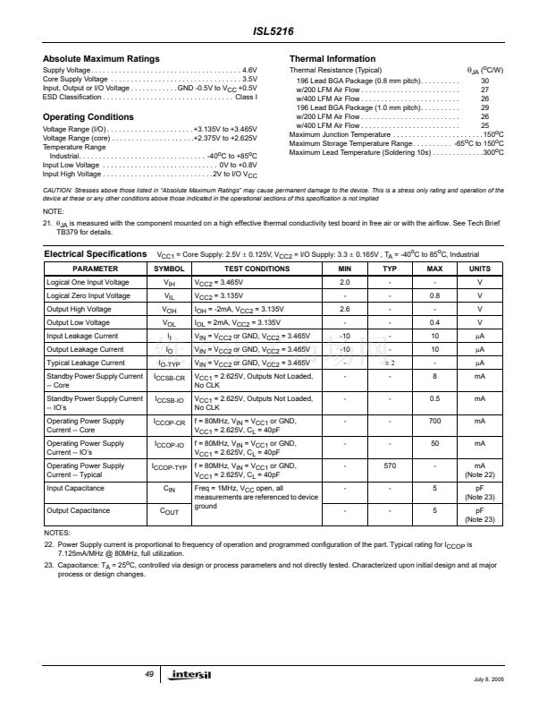
Electrical Specifications
PARAMETER
Logical One Input Voltage
Logical Zero Input Voltage
Output High Voltage
Output Low Voltage
Input Leakage Current
Output Leakage Current
Typical Leakage Current
Standby Power Supply Current
-- Core
Standby Power Supply Current
-- IO鈥檚
Operating Power Supply
Current -- Core
Operating Power Supply
Current -- IO鈥檚
Operating Power Supply
Current -- Typical
Input Capacitance
Output Capacitance
NOTES:
V
CC1
= Core Supply: 2.5V
鹵
0.125V, V
CC2
= I/O Supply: 3.3
鹵
0.165V , T
A
= -40
o
C to 85
o
C, Industrial
SYMBOL
V
IH
V
IL
V
OH
V
OL
I
I
I
O
I
O-TYP
I
CCSB-CR
I
CCSB-IO
I
CCOP-CR
I
CCOP-IO
I
CCOP-TYP
C
IN
C
OUT
TEST CONDITIONS
V
CC2
= 3.465V
V
CC2
= 3.135V
I
OH
= -2mA, V
CC2
= 3.135V
I
OL
= 2mA, V
CC2
= 3.135V
V
IN
= V
CC2
or GND, V
CC2
= 3.465V
V
IN
= V
CC2
or GND, V
CC2
= 3.465V
V
IN
= V
CC2
or GND, V
CC2
= 3.465V
V
CC1
= 2.625V, Outputs Not Loaded,
No CLK
V
CC1
= 2.625V, Outputs Not Loaded,
No CLK
f = 80MHz, V
IN
= V
CC1
or GND,
V
CC1
= 2.625V, C
L
= 40pF
f = 80MHz, V
IN
= V
CC1
or GND,
V
CC1
= 2.625V, C
L
= 40pF
f = 80MHz, V
IN
= V
CC1
or GND,
V
CC1
= 2.625V, C
L
= 40pF
Freq = 1MHz, V
CC
open, all
measurements are referenced to device
ground
MIN
2.0
-
2.6
-
-10
-10
-
-
-
-
-
-
-
-
TYP
-
-
-
-
-
-
鹵2
-
-
-
-
570
-
-
MAX
-
0.8
-
0.4
10
10
-
8
0.5
700
50
-
5
5
UNITS
V
V
V
V
碌A(chǔ)
碌A(chǔ)
碌A(chǔ)
mA
mA
mA
mA
mA
(Note 22)
pF
(Note 23)
pF
(Note 23)
22. Power Supply current is proportional to frequency of operation and programmed configuration of the part. Typical rating for I
CCOP
is
7.125mA/MHz @ 80MHz, full utilization.
23. Capacitance: T
A
= 25
o
C, controlled via design or process parameters and not directly tested. Characterized upon initial design and at major
process or design changes.
49
July 8, 2005


 1
1
 2
2
 3
3
 4
4
 5
5
 6
6
 7
7
 8
8
 9
9
 10
10
 11
11
 12
12
 13
13
 14
14
 15
15
 16
16
 17
17
 18
18
 19
19
 20
20
 21
21
 22
22
 23
23
 24
24
 25
25
 26
26
 27
27
 28
28
 29
29
 30
30
 31
31
 32
32
 33
33
 34
34
 35
35
 36
36
 37
37
 38
38
 39
39
 40
40
 41
41
 42
42
 43
43
 44
44
 45
45
 46
46
 47
47
 48
48
 49
49
 50
50
 51
51
 52
52
 53
53
 54
54
 55
55
 56
56
 57
57
 58
58
 59
59
 60
60
 61
61
 62
62
 63
63
 64
64
 65
65
