ISL5216
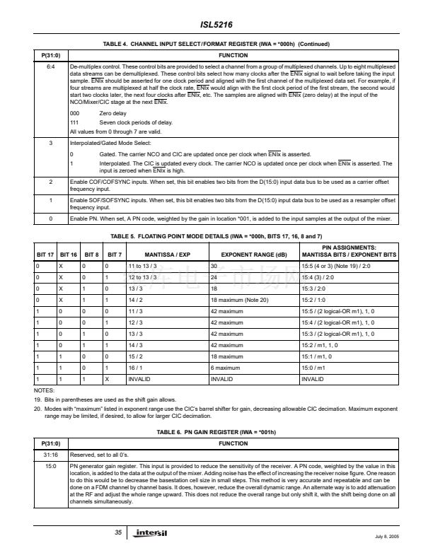
TABLE 4. CHANNEL INPUT SELECT/FORMAT REGISTER (IWA = *000h) (Continued)
P(31:0)
6:4
FUNCTION
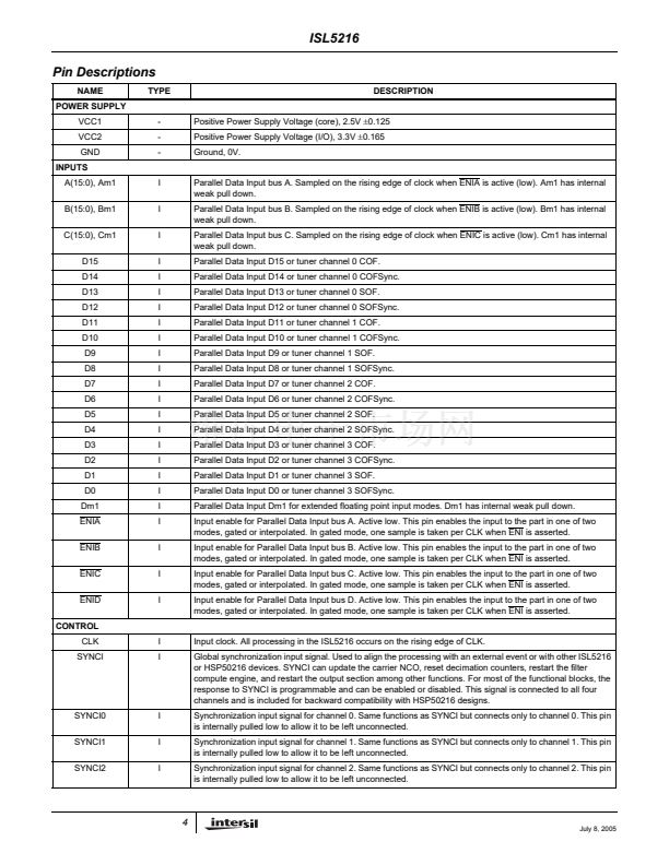
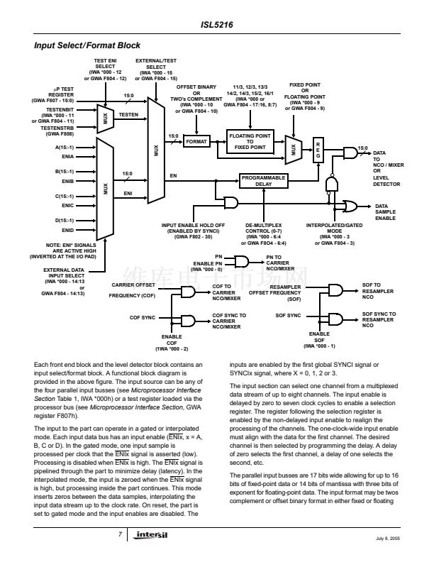
De-multiplex control. These control bits are provided to select a channel from a group of multiplexed channels. Up to eight multiplexed
data streams can be demultiplexed. These control bits select how many clocks after the ENIx signal to wait before taking the input
sample. ENIx should be asserted for one clock period and aligned with the first channel of the multiplexed data set. For example, if
four streams are multiplexed at half the clock rate, ENIx would align with the first clock period of the first stream, the second would
start two clocks later, the next four clocks after ENIx, etc. The samples are aligned with ENIx (zero delay) at the input of the
NCO/Mixer/CIC stage at the next ENIx.
000
111
Zero delay
Seven clock periods of delay.
All values from 0 through 7 are valid.
3
Interpolated/Gated Mode Select:
0
1
2
1
0
Gated. The carrier NCO and CIC are updated once per clock when ENIx is asserted.
Interpolated. The CIC is updated every clock. The carrier NCO is updated once per clock when ENIx is asserted. The
input is zeroed when ENIx is high.
Enable COF/COFSYNC inputs. When set, this bit enables two bits from the D(15:0) input data bus to be used as a carrier offset
frequency input.
Enable SOF/SOFSYNC inputs. When set, this bit enables two bits from the D(15:0) input data bus to be used as a resampler offset
frequency input.
Enable PN. When set, A PN code, weighted by the gain in location *001, is added to the input samples at the output of the mixer.
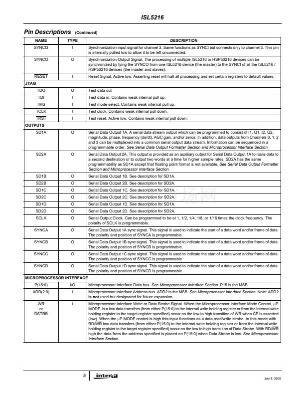
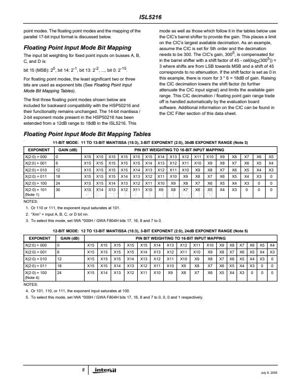
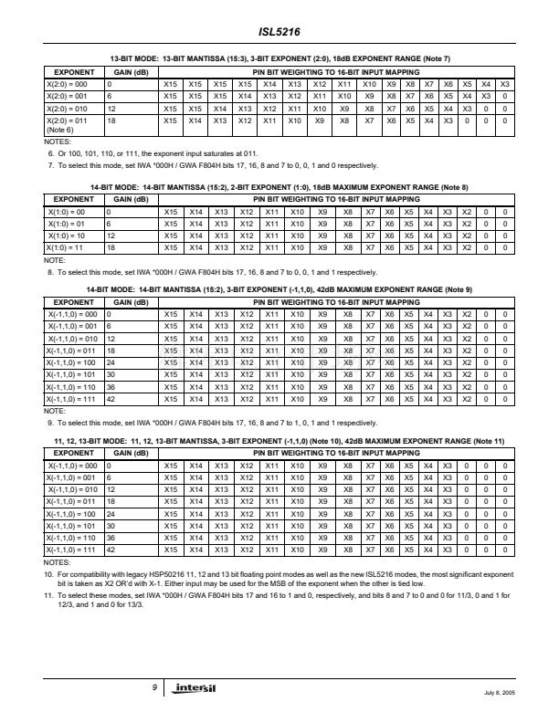
TABLE 5. FLOATING POINT MODE DETAILS (IWA = *000h, BITS 17, 16, 8 and 7)
BIT 17
0
0
0
0
1
1
1
1
1
1
1
NOTES:
BIT 16
X
X
X
X
0
0
0
0
1
1
1
BIT 8
0
0
1
1
0
0
1
1
0
0
1
BIT 7
0
1
0
1
0
1
0
1
0
1
X
MANTISSA / EXP
11 to 13 / 3
12 to 13 / 3
13 / 3
14 / 2
11 / 3
12 / 3
13 / 3
14 / 3
15 / 2
16 / 1
INVALID
30
24
18
EXPONENT RANGE (dB)
PIN ASSIGNMENTS:
MANTISSA BITS / EXPONENT BITS
15:5 (4 or 3) (Note 19) / 2:0
15:4 (3) / 2:0
15:3 / 2:0
15:2 / 1:0
15:5 / (2 logical-OR m1), 1, 0
15:4 / (2 logical-OR m1), 1, 0
15:3 / (2 logical-OR m1), 1, 0
15:2 / m1, 1, 0
15:1 / m1, 0
15:0 / m1
INVALID
18 maximum (Note 20)
42 maximum
42 maximum
42 maximum
42 maximum
18 maximum
6 maximum
INVALID
19. Bits in parentheses are used as the shift gain allows.
20. Modes with 鈥渕aximum鈥?listed in exponent range use the CIC鈥檚 barrel shifter for gain, decreasing allowable CIC decimation. Maximum exponent
range may be limited, if desired, to allow for larger CIC decimation.
TABLE 6. PN GAIN REGISTER (IWA = *001h)
P(31:0)
31:16
15:0
Reserved, set to all 0鈥檚.
PN generator gain register. This input is provided to reduce the sensitivity of the receiver. A PN code, weighted by the value in this
location, is added to the data at the output of the mixer. Adding noise has the effect of increasing the receiver noise figure. One reason
to do this would be to decrease the basestation cell size in small steps. This method is very accurate and repeatable and can be
done on a FDM channel by channel basis. It does, however, reduce the overall dynamic range. An alternate way is to add attenuation
at the RF and adjust the whole range upward. This does not reduce the overall range but only shift it, with the shift being done on all
channels simultaneously.
FUNCTION
35
July 8, 2005


 1
1
 2
2
 3
3
 4
4
 5
5
 6
6
 7
7
 8
8
 9
9
 10
10
 11
11
 12
12
 13
13
 14
14
 15
15
 16
16
 17
17
 18
18
 19
19
 20
20
 21
21
 22
22
 23
23
 24
24
 25
25
 26
26
 27
27
 28
28
 29
29
 30
30
 31
31
 32
32
 33
33
 34
34
 35
35
 36
36
 37
37
 38
38
 39
39
 40
40
 41
41
 42
42
 43
43
 44
44
 45
45
 46
46
 47
47
 48
48
 49
49
 50
50
 51
51
 52
52
 53
53
 54
54
 55
55
 56
56
 57
57
 58
58
 59
59
 60
60
 61
61
 62
62
 63
63
 64
64
 65
65
