or 1 and the settling mode.
accumulator if GWA register F802h bit 27 is set. This sets
bits 15:0) if it is larger than unity.
IWA register *013h bit 8. For mean mode, the gain error is
scaled and used to adjust the gain up or down. This
final gain value asymptotically. This AGC settling mode is
reducing any AM distortion caused by the AGC.
small. This is because the maximum value of the threshold
minus the magnitude is smaller. Also, the settling can be
asymmetric, where the loop may settle faster for 鈥渙ver range鈥?/div>
signals than for 鈥渦nder range鈥?signals (or vice versa).
In some applications, such as burst signals or TDMA signals,
a very fast settling time and/or a more predictable settling
time is desired. The AGC may be turned off or slowed down
after an initial AGC settling period.
The median mode minimizes the settling time. This mode
uses a fixed gain adjustment with only the direction of the
adjustment controlled by the gain error. This makes the
settling time independent of the signal level.
For example, if the loop is set to adjust 0.5dB per output
sample, the loop gain can slew up or down by 16dB in 16
symbol times, assuming a 2-samples-per-symbol output
sample rate. This is called a median settling mode because
the loop settles to where there is an equal number of
magnitude samples above and below the threshold. The
disadvantage of this mode is that the loop will have a wander
(dither) equal to the programmed step size. For this reason,
it is advisable to set one loop gain for fast settling at the
beginning of the burst and the second loop gain for small
adjustments during tracking.
In the median mode, the maximum gain step is
approximately 3dB / output. The step is fixed (it does not
decrease as the error decreases) so a large gain will cause
AM on the output at least that large. The fixed gain step is
set by the programmable AGC loop gain register
IWA *010h.
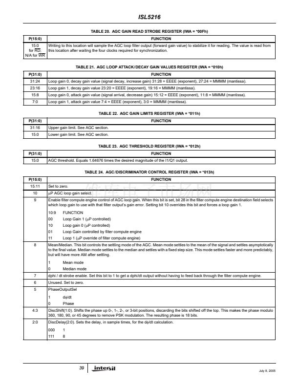
The AGC gain limits register sets the minimum and
maximum limits on the AGC gain. The total AGC gain range
is 96dB, but only a portion of the range should be needed for
most applications. For example, with a 16-bit output to a
processor, the 16 bits may be sufficient for all but 24dB of the
total input range possible. The AGC would only need to have
a range of 24dB. This allows faster settling and the AGC
would be at its maximum gain limit except when a high
power signal was received. The AGC may be disabled by
setting both limits to the same value.
The median settling mode is enabled by setting IWA register
*013h bit 8 to 0 while the mean loop settling mode is
selected by setting bit 8 to 1.
Cartesian to Polar Converter
The Cartesian to Polar converter computes the magnitude
and phase of the I/Q vector. The I and Q inputs are 24 bits
wide. The converter phase output is 18 bits wide and is
routed to the output formatter and frequency discriminator.
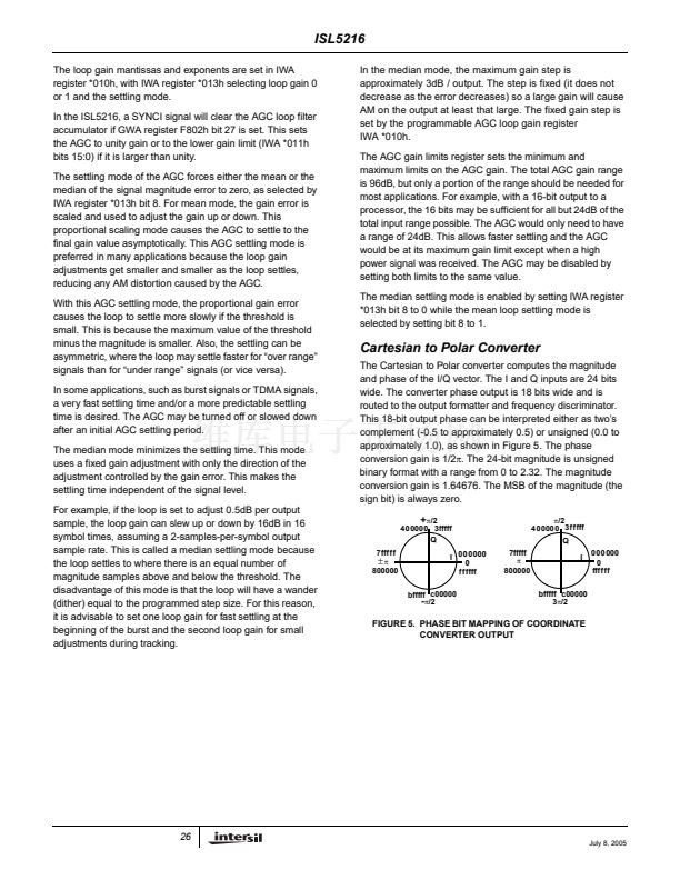
This 18-bit output phase can be interpreted either as two鈥檚
complement (-0.5 to approximately 0.5) or unsigned (0.0 to
approximately 1.0), as shown in Figure 5. The phase
conversion gain is 1/2蟺. The 24-bit magnitude is unsigned
binary format with a range from 0 to 2.32. The magnitude
conversion gain is 1.64676. The MSB of the magnitude (the
sign bit) is always zero.
+
蟺/2
400000 3fffff
Q
7fffff
鹵
蟺
800000
I 000000
0
ffffff
bfffff c00000
-
蟺/2
7fffff
蟺
800000
蟺/2
400000 3fffff
Q
I
000000
0
ffffff
bfffff c00000
3蟺/2
FIGURE 5. PHASE BIT MAPPING OF COORDINATE
CONVERTER OUTPUT
26
July 8, 2005


 1
1
 2
2
 3
3
 4
4
 5
5
 6
6
 7
7
 8
8
 9
9
 10
10
 11
11
 12
12
 13
13
 14
14
 15
15
 16
16
 17
17
 18
18
 19
19
 20
20
 21
21
 22
22
 23
23
 24
24
 25
25
 26
26
 27
27
 28
28
 29
29
 30
30
 31
31
 32
32
 33
33
 34
34
 35
35
 36
36
 37
37
 38
38
 39
39
 40
40
 41
41
 42
42
 43
43
 44
44
 45
45
 46
46
 47
47
 48
48
 49
49
 50
50
 51
51
 52
52
 53
53
 54
54
 55
55
 56
56
 57
57
 58
58
 59
59
 60
60
 61
61
 62
62
 63
63
 64
64
 65
65
