ISL5216
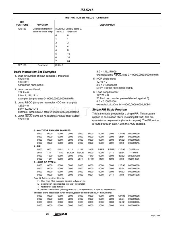
INSTRUCTION BIT FIELDS (Continued)
BIT
POSITIONS
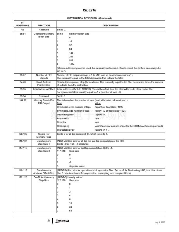
63
66:64
FUNCTION
Reserved
Coefficient Memory
Block Size
Set to 0.
66:64
0
1
2
3
4
5
6
7
Memory Block Size
8
16
32
64
128
256
512
1024
DESCRIPTION
(Modulo addressing can be used, but is usually not needed. If not needed this bit field can always be
set to 7).
75:67
84:76
93:85
95:94
104:96
Number of FIR
Outputs
Read Address
Pointer Step
Initial Address Offset
Reserved
Memory Reads Per
FIR Output
Number of FIR outputs (range is 1 to 512, load w/ desired value minus 1).
This is usually equal to the total decimation that follows the filter.
Read address pointer step (for next run). This is usually equal to the filter decimation times the number
of outputs from the instruction.
Initial address offset (to ADDRB). This is the offset from the start address to other end of filter.
For symmetric filters, usually equal to -1 x (number of taps -1).
Set to 0
This is based on the number of taps (load with value below minus 1).
Value
Type
Symmetric, even number of taps
Symmetric, odd number of taps
Decimating HBF
Asymmetric
Complex
Resampling
Interpolating HBF
106:105
115:107
117:116
Clocks Per
Memory Read
Data Memory
Step Size 1
Data Memory
Step Size 2
(taps/2) or floor((taps+1)/2).
(taps+1)/2 or floor((taps+1)/2).
(taps+5)/4.
taps.
taps .
taps/phase (six taps per phase for the ROM鈥檇 coefficients provided).
(taps+5)/4-1 .
Set to 0 for all but complex FIR, which is set to 1.
(ADDRA) Step size for all but the last tap computation of the FIR.
Set to -2 for HBF, -1 otherwise.
(ADDRA) Step size for last tap computation. Set to -1.
117:116
Step size
0
1
2
3
0
-1
-2
step size value.
119:118
122:120
Data Memory
Address Offset Step
Coefficient Memory
Step Size
(ADDRB) Step size for opposite end of symmetric filter. Set to +2 for Decimating HBF, to +1 for others
(the B data is not used for asymmetric, resampling, and complex filters).
(ADDRC) Usually set to 1.
122:120
Step size
0
1
2
3
4
5
6
7
0
1
2
4
8
16
32
64
21
July 8, 2005


 1
1
 2
2
 3
3
 4
4
 5
5
 6
6
 7
7
 8
8
 9
9
 10
10
 11
11
 12
12
 13
13
 14
14
 15
15
 16
16
 17
17
 18
18
 19
19
 20
20
 21
21
 22
22
 23
23
 24
24
 25
25
 26
26
 27
27
 28
28
 29
29
 30
30
 31
31
 32
32
 33
33
 34
34
 35
35
 36
36
 37
37
 38
38
 39
39
 40
40
 41
41
 42
42
 43
43
 44
44
 45
45
 46
46
 47
47
 48
48
 49
49
 50
50
 51
51
 52
52
 53
53
 54
54
 55
55
 56
56
 57
57
 58
58
 59
59
 60
60
 61
61
 62
62
 63
63
 64
64
 65
65
