tables for each operating mode. Load power dissipation is
not a factor since this is an on hook mode. Some
applications may specify a standby current. The standby
telephone electronics.
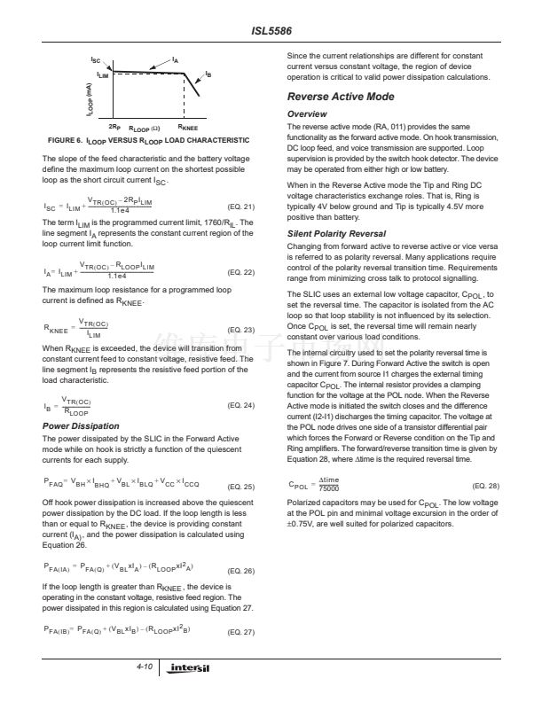
. Equation 17 illustrates the power
contribution is zero when the standby line current is zero.
鈥?/div>
49
+
1
+
I
SLC
x1200
)
(EQ. 17)
-
+
K
S
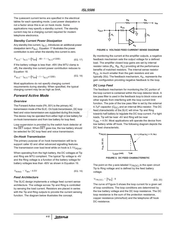
FIGURE 4. VOLTAGE FEED CURRENT SENSE DIAGRAM
If the battery voltage is less than -49V (the MTU clamp is
off), the standby line current power contribution reduces to
Equation 18.
P
SLC
=
I
SLC
脳 (
V
BH
+
1
+
I
SLC
x1200
)
(EQ. 18)
By monitoring the current at the amplifier outputs, a negative
feedback mechanism sets the output voltage for a defined
load. The amplifier closed loop gains are set by internal
resistor ratios (R
A
, R
B
, R
C
) providing all the performance
benefits of matched resistors. The internal sense resistor
R
CS
, is much smaller than the gain resistors and are
typically 20鈩? The feedback mechanism, K
S
, represents the
gain configuration providing negative feedback to the loop.
Most applications do not specify charging current
requirements during standby. When specified, the typical
charging current may be as high as 5mA.
DC Loop Feed
The feedback mechanism for monitoring the DC portion of
the loop current is contained within the loop detector block. A
low pass filter is used in the feedback loop to block voice and
other signals from interfering with the loop current limit
function. The pole of the low pass filter is set by the external
4.7碌F capacitor (C
DC)
and an internal 8K鈩?resistor. The DC
feed characteristic of the SLIC will drive Tip and Ring
towards half battery to regulate the DC loop current. For light
loads, Tip will be near -4V and Ring will be near
V
VBL
+ 4.5V. Most applications will operate the device from
low battery while off hook. The following diagram depicts the
DC feed characteristic.
V
TR(OC)
m = (鈭哣
TR
/鈭咺
L
) = 11.1k鈩?/div>
Forward Active Mode
Overview
The Forward Active mode (FA, 001) is the primary AC
transmission mode of the SLIC. On hook transmission, DC loop
feed and voice transmission are supported during this mode.
The device may be operated from either high or low battery for
on-hook transmission and from low battery for loop feed.
Loop supervision is provided by the switch hook detector at
the DET output. When DET goes low, the low battery should
be selected for DC loop feed and voice transmission.
On-Hook Transmission
The primary purpose of on hook transmission will be to
support caller ID and other advanced signalling features.
The transmission over load level while on hook is 3.1V
PEAK
.
When operating from the high battery, the DC voltages at Tip
and Ring are MTU compliant. The typical Tip voltage is -4V
and the Ring voltage is a function of the battery voltage for
battery voltages less than -60V as shown in Equation 19.
V
RING
=
V
BH
+
4.5V
(EQ. 19)
V
TR
, DC (V)
I
LOOP
(mA)
I
LIM
FIGURE 5. DC FEED CHARACTERISTIC
The point on the y-axis labeled V
TR(OC)
is the open circuit
Tip to Ring voltage and is defined by the feed battery
voltage.
V
TR
(
OC
)
=
V
BL
鈥?/div>
9
(EQ. 20)
Feed Architecture
The SLIC design implements a voltage feed current sense
architecture. The voltage across Tip and Ring is controlled
by sensing the load current. Resistors are placed in series
with the Tip and Ring outputs to provide the current sensing
function. The diagram below illustrates the concept.
The curve of Figure 5 shows the loop current for a given set
of loop conditions. The loop conditions are determined by
the low battery voltage and the DC loop resistance. The DC
loop resistance is the sum of the protection resistance,
copper resistance (ohms/foot) and the telephone off hook
DC resistance.
4-9


 1
1
 2
2
 3
3
 4
4
 5
5
 6
6
 7
7
 8
8
 9
9
 10
10
 11
11
 12
12
 13
13
 14
14
 15
15
 16
16
 17
17
 18
18
 19
19
 20
20
