ISL5740
Absolute Maximum Ratings
T
A
= 25
o
C
Thermal Information
Thermal Resistance (Typical, Note 1)
胃
JA
(
o
C/W)
ISL5740IN . . . . . . . . . . . . . . . . . . . . . . . . . . . . . . . .
70
Maximum Junction Temperature . . . . . . . . . . . . . . . . . . . . . . .150
o
C
Maximum Storage Temperature Range . . . . . . . . . . -65
o
C to 150
o
C
Maximum Lead Temperature (Soldering 10s) . . . . . . . . . . . . .300
o
C
(Lead Tips Only)
Supply Voltage, AV
CC
or DV
CC
to AGND or DGND . . . . . . . . . . .4V
DGND to AGND . . . . . . . . . . . . . . . . . . . . . . . . . . . . . . . . . . . . . . . . 0.3V
Digital I/O Pins . . . . . . . . . . . . . . . . . . . . . . . . . . . . . DGND to DV
CC
Analog I/O Pins . . . . . . . . . . . . . . . . . . . . . . . . . . . . AGND to AV
CC
Operating Conditions
Temperature Range
ISL5740IN . . . . . . . . . . . . . . . . . . . . . . . . . . . . . . . -40
o
C to 85
o
C
CAUTION: Stresses above those listed in 鈥淎bsolute Maximum Ratings鈥?may cause permanent damage to the device. This is a stress only rating and operation of the
device at these or any other conditions above those indicated in the operational sections of this speci鏗乧ation is not implied.
NOTE:
1.
胃
JA
is measured with the component mounted on an evaluation PC board in free air.
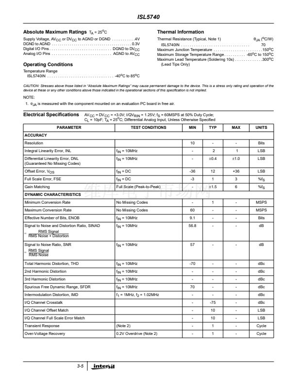
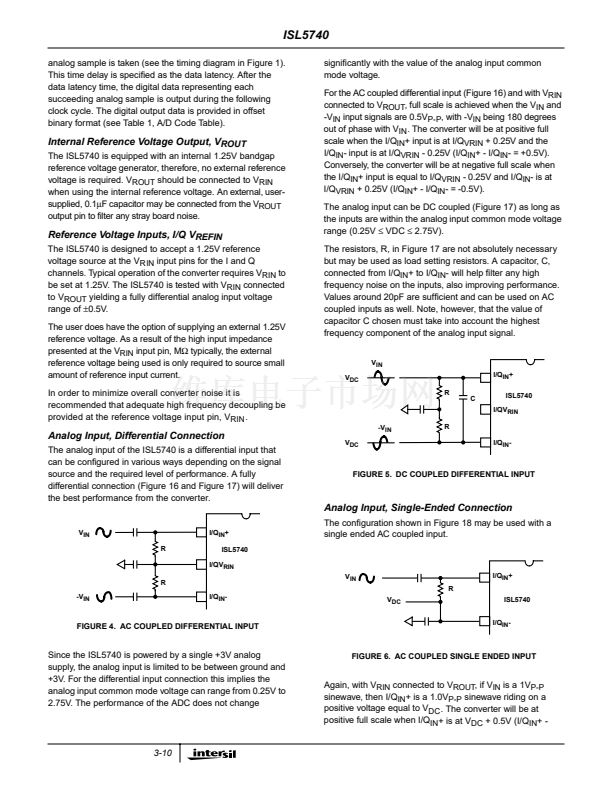
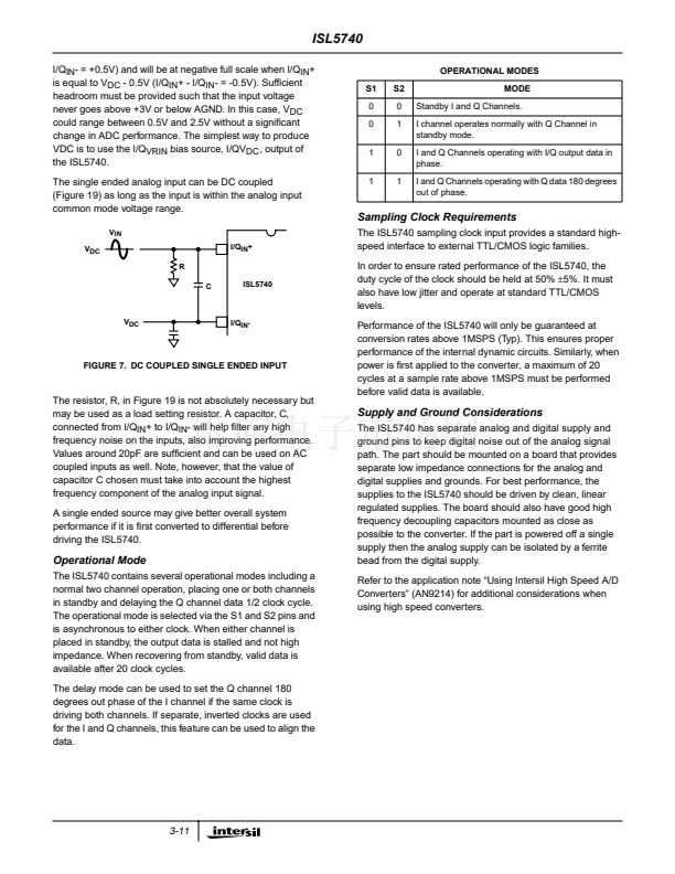
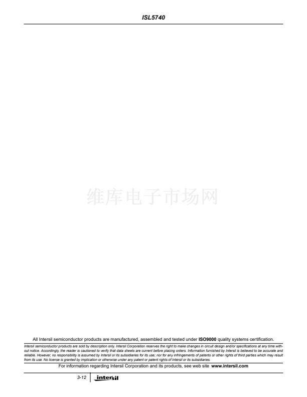
Electrical Speci鏗乧ations
PARAMETER
ACCURACY
Resolution
Integral Linearity Error, INL
Differential Linearity Error, DNL
(Guaranteed No Missing Codes)
Offset Error, V
OS
Full Scale Error, FSE
Gain Matching
DYNAMIC CHARACTERISTICS
Minimum Conversion Rate
Maximum Conversion Rate
Effective Number of Bits, ENOB
AV
CC
= DV
CC
= +3.0V; I/QV
RIN
= 1.25V; f
S
= 60MSPS at 50% Duty Cycle;
C
L
= 10pF; T
A
= 25
o
C; Differential Analog Input, Unless Otherwise Speci鏗乪d
TEST CONDITIONS
MIN
TYP
MAX
UNITS
10
f
IN
= 10MHz
f
IN
= 10MHz
f
IN
= DC
f
IN
= DC
Full Scale (Peak-to-Peak)
-
-
-36
-3
-
-
2
鹵0.4
12
1
鹵1.5
-
1
鹵1.0
+36
3
6
Bits
LSB
LSB
LSB
%f
S
%f
S
No Missing Codes
No Missing Codes
f
IN
= 10MHz
f
IN
= 10MHz
-
60
9.1
56.8
1
-
-
-
-
-
-
-
MSPS
MSPS
Bits
dB
Signal to Noise and Distortion Ratio, SINAD
RMS Signal
= -------------------------------------------------------------
-
RMS Noise + Distortion
Signal to Noise Ratio, SNR
RMS Signal
= ------------------------------
-
RMS Noise
Total Harmonic Distortion, THD
2nd Harmonic Distortion
3rd Harmonic Distortion
Spurious Free Dynamic Range, SFDR
Intermodulation Distortion, IMD
I/Q Channel Crosstalk
I/Q Channel Offset Match
I/Q Channel Full Scale Error Match
Transient Response
Over-Voltage Recovery
f
IN
= 10MHz
57
-
-
dB
f
IN
= 10MHz
f
IN
= 10MHz
f
IN
= 10MHz
f
IN
= 10MHz
f
1
= 1MHz, f
2
= 1.02MHz
-70
-
-
70
-
-
-
-
-
-
-
-
-
-75
10
10
1
1
-
-
-
-
-
-
-
-
-
-
dBc
dBc
dBc
dBc
dBc
dBc
LSB
LSB
Cycle
Cycle
(Note 2)
0.2V Overdrive (Note 2)
-
-
3-5


 1
1
 2
2
 3
3
 4
4
 5
5
 6
6
 7
7
 8
8
 9
9
 10
10
 11
11
 12
12
