鈮?/div>
2.75V).
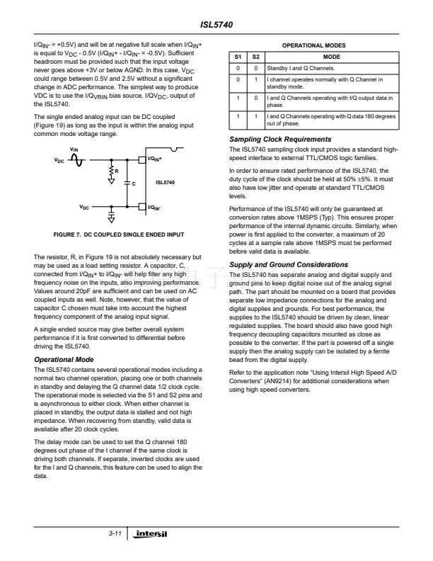
The resistors, R, in Figure 17 are not absolutely necessary
but may be used as load setting resistors. A capacitor, C,
connected from I/Q
IN
+ to I/Q
IN
- will help 鏗乴ter any high
frequency noise on the inputs, also improving performance.
Values around 20pF are suf鏗乧ient and can be used on AC
coupled inputs as well. Note, however, that the value of
capacitor C chosen must take into account the highest
frequency component of the analog input signal.
V
IN
V
DC
R
C
I/Q
IN
+
ISL5740
I/QV
RIN
-V
IN
V
DC
R
I/Q
IN
-
Internal Reference Voltage Output, V
ROUT
The ISL5740 is equipped with an internal 1.25V bandgap
reference voltage generator, therefore, no external reference
voltage is required. V
ROUT
should be connected to V
RIN
when using the internal reference voltage. An external, user-
supplied, 0.1碌F capacitor may be connected from the V
ROUT
output pin to filter any stray board noise.
Reference Voltage Inputs, I/Q V
REFIN
The ISL5740 is designed to accept a 1.25V reference
voltage source at the V
RIN
input pins for the I and Q
channels. Typical operation of the converter requires V
RIN
to
be set at 1.25V. The ISL5740 is tested with V
RIN
connected
to V
ROUT
yielding a fully differential analog input voltage
range of
鹵0.5V.
The user does have the option of supplying an external 1.25V
reference voltage. As a result of the high input impedance
presented at the V
RIN
input pin, M鈩?typically, the external
reference voltage being used is only required to source small
amount of reference input current.
In order to minimize overall converter noise it is
recommended that adequate high frequency decoupling be
provided at the reference voltage input pin, V
RIN
.
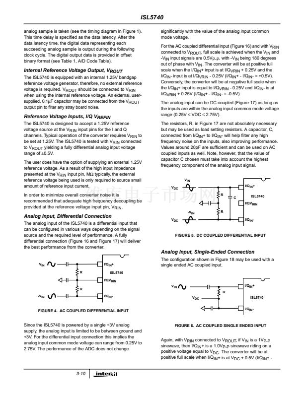
Analog Input, Differential Connection
The analog input of the ISL5740 is a differential input that
can be con鏗乬ured in various ways depending on the signal
source and the required level of performance. A fully
differential connection (Figure 16 and Figure 17) will deliver
the best performance from the converter.
FIGURE 5. DC COUPLED DIFFERENTIAL INPUT
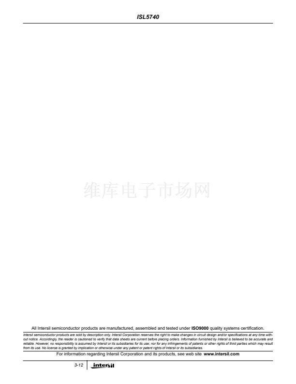
Analog Input, Single-Ended Connection
V
IN
R
I/Q
IN
+
ISL5740
I/QV
RIN
R
-V
IN
I/Q
IN
-
V
IN
R
V
DC
ISL5740
I/Q
IN
-
I/Q
IN
+
The con鏗乬uration shown in Figure 18 may be used with a
single ended AC coupled input.
FIGURE 4. AC COUPLED DIFFERENTIAL INPUT
Since the ISL5740 is powered by a single +3V analog
supply, the analog input is limited to be between ground and
+3V. For the differential input connection this implies the
analog input common mode voltage can range from 0.25V to
2.75V. The performance of the ADC does not change
FIGURE 6. AC COUPLED SINGLE ENDED INPUT
Again, with V
RIN
connected to V
ROUT
, if V
IN
is a 1V
P-P
sinewave, then I/Q
IN
+ is a 1.0V
P-P
sinewave riding on a
positive voltage equal to V
DC
. The converter will be at
positive full scale when I/Q
IN
+ is at V
DC
+ 0.5V (I/Q
IN
+ -
3-10


 1
1
 2
2
 3
3
 4
4
 5
5
 6
6
 7
7
 8
8
 9
9
 10
10
 11
11
 12
12
