M14C64, M14C32
Figure 5. I
2
C Bus Protocol
SCL
SDA
START
CONDITION
SDA
INPUT
SDA
CHANGE
STOP
CONDITION
SCL
1
2
3
7
8
9
SDA
MSB
ACK
START
CONDITION
SCL
1
2
3
7
8
9
SDA
MSB
ACK
STOP
CONDITION
AI00792
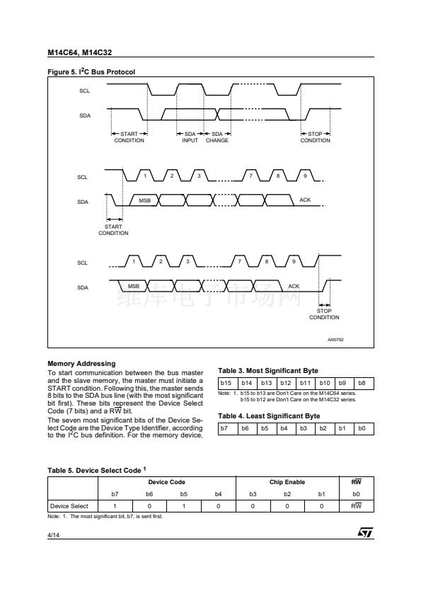
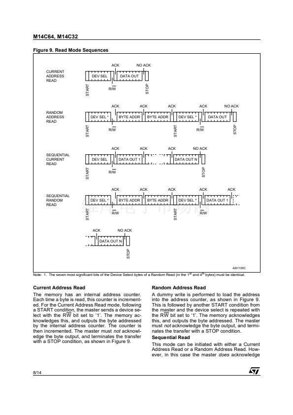
Memory Addressing
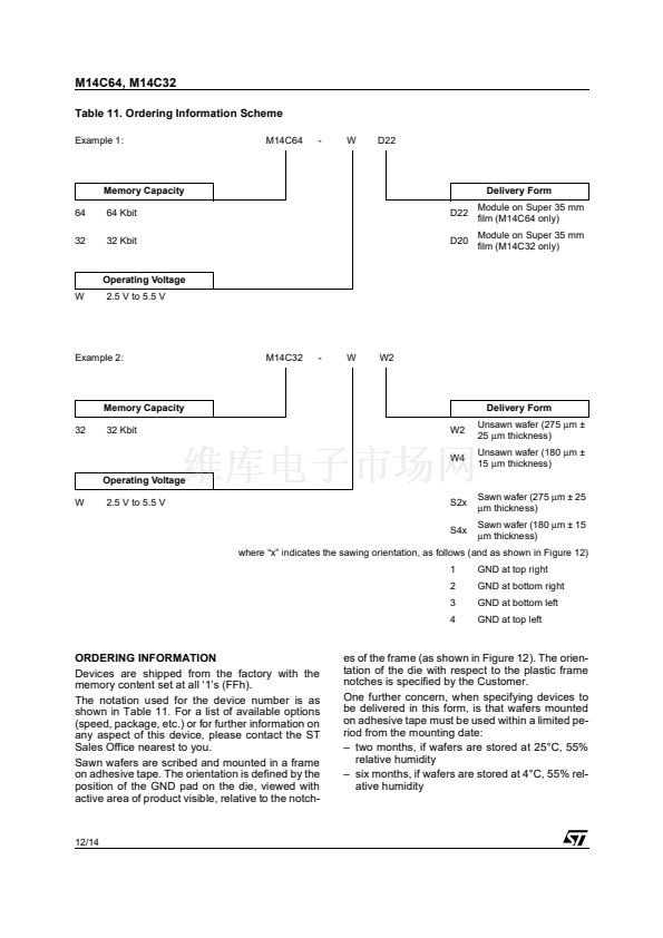
To start communication between the bus master
and the slave memory, the master must initiate a
START condition. Following this, the master sends
8 bits to the SDA bus line (with the most significant
bit first). These bits represent the Device Select
Code (7 bits) and a RW bit.
The seven most significant bits of the Device Se-
lect Code are the Device Type Identifier, according
to the I
2
C bus definition. For the memory device,
Table 3. Most Significant Byte
b15
b14
b13
b12
b11
b10
b9
b8
Note: 1. b15 to b13 are Don鈥檛 Care on the M14C64 series.
b15 to b12 are Don鈥檛 Care on the M14C32 series.
Table 4. Least Significant Byte
b7
b6
b5
b4
b3
b2
b1
b0
Table 5. Device Select Code
1
Device Code
b7
Device Select
1
b6
0
b5
1
b4
0
b3
0
Chip Enable
b2
0
b1
0
RW
b0
RW
Note: 1. The most significant bit, b7, is sent first.
4/14


 1
1
 2
2
 3
3
 4
4
 5
5
 6
6
 7
7
 8
8
 9
9
 10
10
 11
11
 12
12
 13
13
 14
14
