MP4009
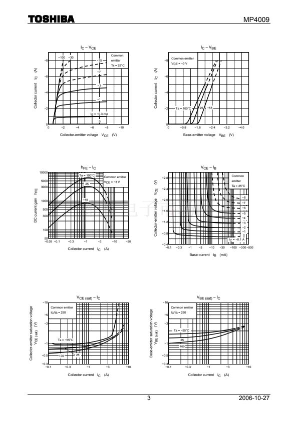
r
th
鈥?t
w
300
Transient thermal resistance r
th
(擄C/W)
Curves should be applied in thermal
100
limited area. (Single nonrepetitive pulse)
The figure shows thermal resistance per
device versus pulse width.
(4)
(1)
(3)
(2)
30
10
3
1
0.3
0.001
-No heat sink/Attached on a circuit board-
(1) 1-device operation
(2) 2-device operation
(3) 3-device operation
Circuit board
(4) 4-device operation
0.01
0.1
1
10
100
1000
Pulse width
t
w
(s)
Safe Operating Area
鈭?0
8
P
T
鈥?Ta
(1) 1-device operation
(2) 2-device operation
(3) 3-device operation
(4) 4-device operation
Attached on a circuit board
鈭?0
鈭?
IC max (pulsed)*
10 ms*
1 ms*
100
渭s*
P
T
(W)
Total power dissipation
6
(A)
鈭?
4
(4)
(3)
(2)
Circuit board
Collector current I
C
鈭?
鈭?.5
鈭?.3
2
(1)
0
0
40
80
120
160
200
Ambient temperature Ta (擄C)
鈭?.1
*: Single nonrepetitive pulse
Ta = 25擄C
VCEO max
鈭?0
鈭?00
鈭?00
鈭?.05
Curves must be derated linearly
with increase in temperature.
鈭?.03
鈭?
鈭?
鈭?0
Collector-emitter voltage V
CE
(V)
螖T
j
鈥?P
T
160
Junction temperature increase
螖T
j
(擄C)
(1)
120
(2)
(3)
(4)
80
Circuit board
Attached on a circuit board
40
(1) 1-device operation
(2) 2-device operation
(3) 3-device operation
(4) 4-device operation
1
2
3
4
5
0
0
Total power dissipation
P
T
(W)
4
2006-10-27


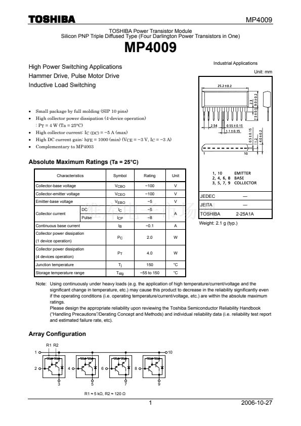 1
1
 2
2
 3
3
 4
4
 5
5
