AT27C512R
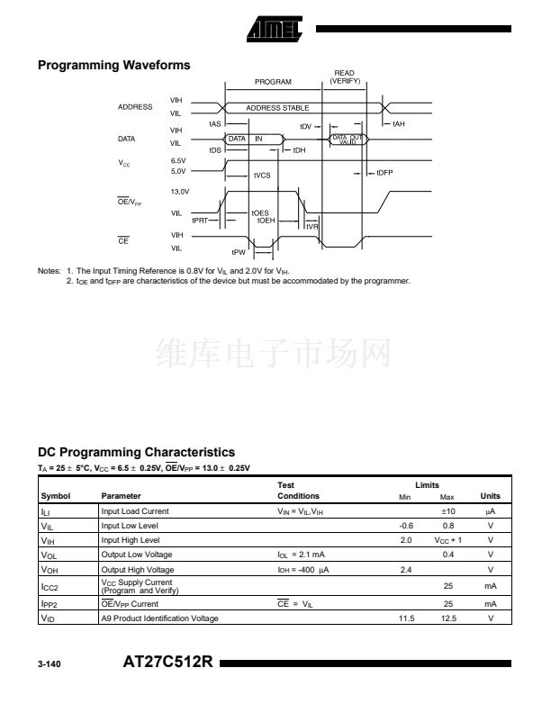
AC Waveforms for Read Operation
(1)
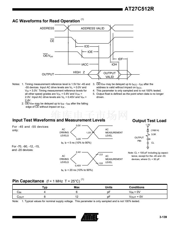
Notes: 1. Timing measurement reference level is 1.5V for -45 and
-55 devices. Input AC drive levels are V
IL
= 0.0V and
V
IH
= 3.0V. Timing measurement reference levels for
all other speed grades are V
OL
= 0.8V and V
OH
=
2.0V. Input AC drive levels are V
IL
= 0.45V and V
IH
=
2.4V.
2. OE/V
PP
may be delayed up to t
CE
- t
OE
after the falling
edge of CE without impact on t
CE
.
3. OE/V
PP
may be delayed up to t
ACC
- t
OE
after the
address is valid without impact on t
ACC
.
4. This parameter is only sampled and is not 100% tested.
5. Output float is defined as the point when data is no longer
driven.
Input Test Waveforms and Measurement Levels
For -45 and -55 devices
only:
Output Test Load
t
R
, t
F
< 5 ns (10% to 90%)
For -70, -90, -12, -15,
and -20 devices:
Note: CL = 100 pF including jig capaci-
tance, except for the -45 and -55
devices, where CL = 30 pF.
t
R
, t
F
< 20 ns (10% to 90%)
Pin Capacitance
(f = 1 MHz T = 25擄C)
Typ
C
IN
C
OUT
Note:
(1)
Max
6
12
Units
pF
pF
Conditions
V
IN
= 0V
V
OUT
= 0V
4
8
1. Typical values for nominal supply voltage. This parameter is only sampled and is not 100% tested.
3-139


 1
1
 2
2
 3
3
 4
4
 5
5
 6
6
 7
7
 8
8
 9
9
