COMLINK鈩?SERIES
CY2CC910
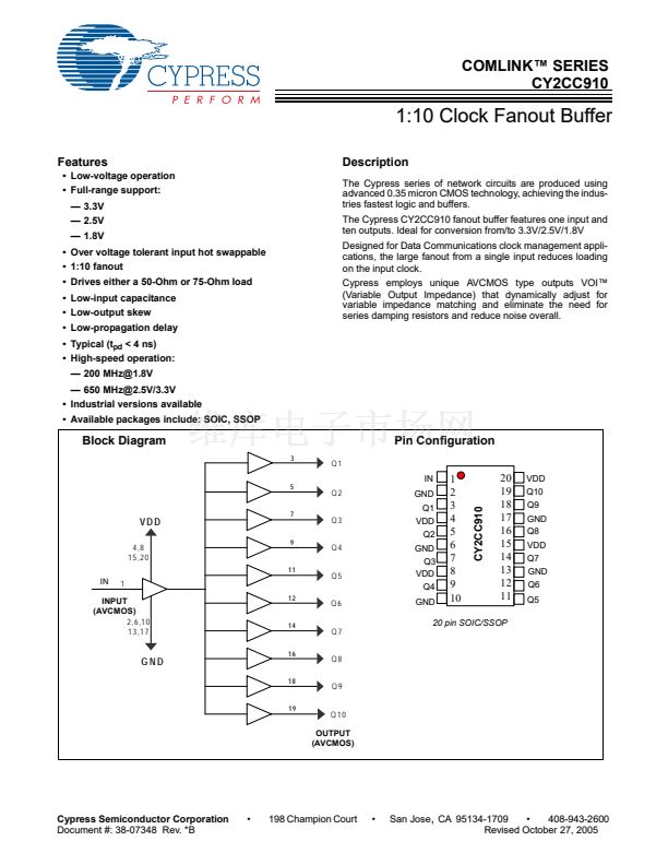
Pin Description
Pin Number
1
2,6,10,13,17
4,8,15,20
3,5,7,9,11,12,14,16,18,19
IN
Pin Name
Input
Ground
Power Supply
Output
Description
G
ND
V
DD
Q1,Q2,Q3,Q4,Q5,Q6,Q7,Q8,Q9,Q10
Maximum Ratings
[1]
Storage Temperature: ................................. 鈥?5擄C to +150擄C
Ambient Temperature:................................... 鈥?0擄C to +85擄C
Supply Voltage to Ground Potential
V
CC
.................................................................. 鈥?.5V to 4.6V
Input ................................................................. 鈥?.5V to 5.8V
Supply Voltage to Ground Potential
(Outputs only) ........................................... 鈥?.5V to V
DD
+ 1V
DC Output Voltage.................................... 鈥?.5V to V
DD
+ 1V
Power Dissipation........................................................ 0.75W
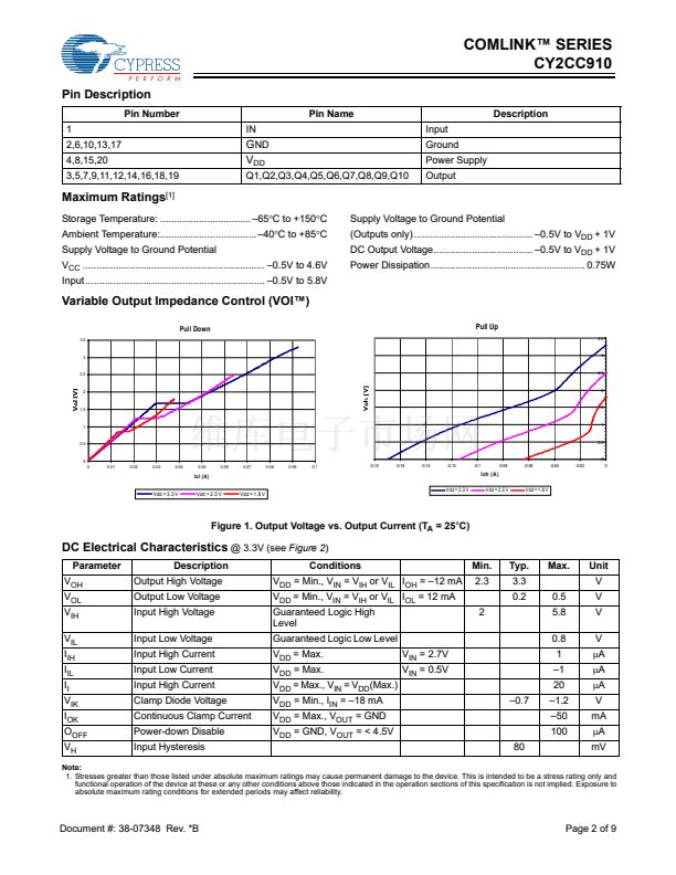
Variable Output Impedance Control (VOI鈩?
Pull Down
3.5
Pull Up
3.5
3
3
2.5
2.5
2
2
1.5
1.5
1
1
0.5
0.5
0
0
0.01
0.02
0.03
0.04
0.05
0.06
0.07
0.08
0.09
0.1
0
-0.18
-0.16
-0.14
-0.12
-0.1
-0.08
-0.06
-0.04
-0.02
0
Iol (A)
Vdd = 3.3 V
Vdd = 2.5 V
Vdd = 1.8 V
Vdd = 3.3 V
Ioh (A)
Vdd = 2.5 V
Vdd = 1.8 V
Figure 1. Output Voltage vs. Output Current (T
A
= 25擄C)
DC Electrical Characteristics
@ 3.3V (see
Figure 2)
Parameter
V
OH
V
OL
V
IH
V
IL
I
IH
I
IL
I
I
V
IK
I
OK
O
OFF
V
H
Description
Output High Voltage
Output Low Voltage
Input High Voltage
Input Low Voltage
Input High Current
Input Low Current
Input High Current
Clamp Diode Voltage
Continuous Clamp Current
Power-down Disable
Input Hysteresis
Conditions
V
DD
= Min., V
IN
= V
IH
or V
IL
I
OH
= 鈥?2 mA
V
DD
= Min., V
IN
= V
IH
or V
IL
I
OL
= 12 mA
Guaranteed Logic High
Level
Guaranteed Logic Low Level
V
DD
= Max.
V
DD
= Max.
V
DD
= Max., V
IN
= V
DD
(Max.)
V
DD
= Min., I
IN
= 鈥?8 mA
V
DD
= Max., V
OUT
= GND
V
DD
= GND, V
OUT
= < 4.5V
80
鈥?.7
V
IN
= 2.7V
V
IN
= 0.5V
2
Min.
2.3
Typ.
3.3
0.2
0.5
5.8
0.8
1
鈥?
20
鈥?.2
鈥?0
100
Max.
Unit
V
V
V
V
碌A
碌A
碌A
V
mA
碌A
mV
Note:
1. Stresses greater than those listed under absolute maximum ratings may cause permanent damage to the device. This is intended to be a stress rating only and
functional operation of the device at these or any other conditions above those indicated in the operation sections of this specification is not implied. Exposure to
absolute maximum rating conditions for extended periods may affect reliability.
Document #: 38-07348 Rev. *B
Page 2 of 9


 1
1
 2
2
 3
3
 4
4
 5
5
 6
6
 7
7
 8
8
 9
9
