ISL6537
will immediately shut down when the Fault Counter reaches
a count of 5 at any other time.
The 16384 counts that are required to reset the Fault Reset
Counter represent 8 soft-start cycles, as one soft-start cycle
is 2048 clock cycles. This allows the ISL6537 to attempt at
least one full soft-start sequence to restart the faulted
regulators.
When attempting to restart a faulted regulator, the ISL6537
will follow the preset start up sequencing. If a regulator is
already in regulation, then it will not be affected by the start
up sequencing.
Thermal Protection (S0/S3 State)
If the ISL6537 IC junction temperature reaches a nominal
temperature of 140擄C, all regulators will be disabled. The
ISL6537 will not re-enable the outputs until the junction
temperature drops below 110擄C and either the bias voltage is
toggled in order to initiate a POR or the SLP_S5 signal is
forced LOW and then back to HIGH.
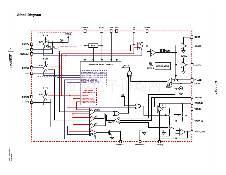
Shoot-Through Protection
A shoot-through condition occurs when both the upper and
lower MOSFETs are turned on simultaneously, effectively
shorting the input voltage to ground. To protect from a shoot-
through condition, the ISL6537 incorporates specialized
circuitry on the V
DDQ
regulator which insures that
complementary MOSFETs are not ON simultaneously.
The adaptive shoot-through protection utilized by the V
DDQ
regulator looks at the lower gate drive pin, LGATE, and the
upper gate drive pin, UGATE, to determine whether a
MOSFET is ON or OFF. If the voltage from UGATE or from
LGATE to GND is less than 0.8V, then the respective
MOSFET is defined as being OFF and the other MOSFET is
allowed to turned ON. This method allows the V
DDQ
regulator to both source and sink current.
Since the voltage of the MOSFET gates are being measured
to determine the state of the MOSFET, the designer is
encouraged to consider the repercussions of introducing
external components between the gate drivers and their
respective MOSFET gates before actually implementing
such measures. Doing so may interfere with the shoot-
through protection.
V
DDQ
Over Current Protection
The over-current function protects the switching converter
from a shorted output by using the upper MOSFET on-
resistance, r
DS(ON)
, to monitor the current. This method
enhances the converter鈥檚 efficiency and reduces cost by
eliminating a current sensing resistor.
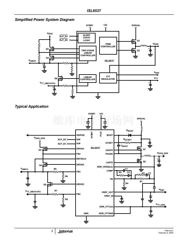
The over-current function cycles the soft-start function in a
hiccup mode to provide fault protection. A resistor (R
OCSET
)
programs the over-current trip level (see Typical Application
diagrams on pages 3 and 4). An internal 20碌A(chǔ) (typical) current
sink develops a voltage across R
OCSET
that is referenced to
the converter input voltage. When the voltage across the
upper MOSFET (also referenced to the converter input
voltage) exceeds the voltage across R
OCSET
, the over-
current function initiates a soft-start sequence. The initiation of
soft start may affect other regulators. The V
TT_DDR
regulator
is directly affected as it receives it鈥檚 reference and input from
V
DDQ
.
The over-current function will trip at a peak inductor current
(I
PEAK)
determined by:
I
OCSET
x R
OCSET
I
PEAK
= ----------------------------------------------------
-
r
DS
(
ON
)
Application Guidelines
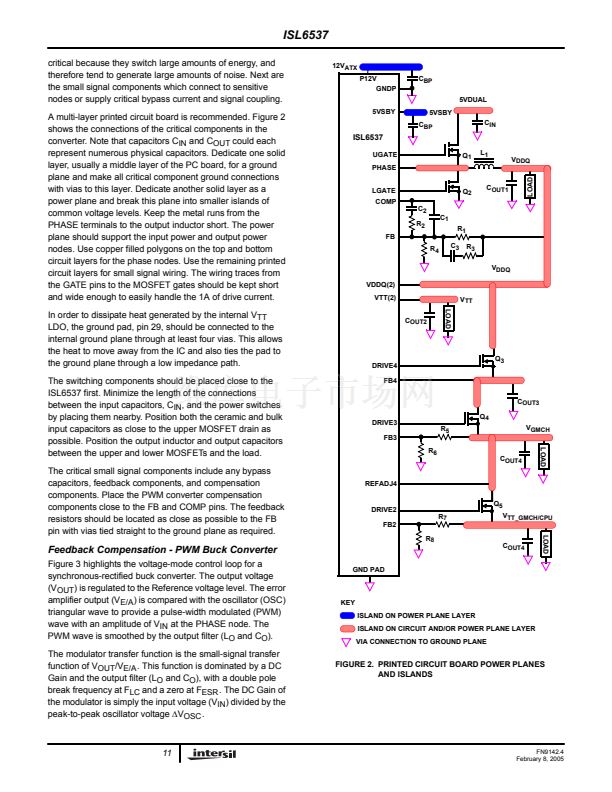
Layout Considerations
Layout is very important in high frequency switching
converter design. With power devices switching efficiently at
250kHz, the resulting current transitions from one device to
another cause voltage spikes across the interconnecting
impedances and parasitic circuit elements. These voltage
spikes can degrade efficiency, radiate noise into the circuit,
and lead to device over-voltage stress. Careful component
layout and printed circuit board design minimizes these
voltage spikes.
As an example, consider the turn-off transition of the control
MOSFET. Prior to turn-off, the MOSFET is carrying the full
load current. During turn-off, current stops flowing in the
MOSFET and is picked up by the lower MOSFET. Any
parasitic inductance in the switched current path generates a
large voltage spike during the switching interval. Careful
component selection, tight layout of the critical components,
and short, wide traces minimizes the magnitude of voltage
spikes.
There are two sets of critical components in the ISL6537
switching converter. The switching components are the most
where I
OCSET
is the internal OCSET current source (20碌A(chǔ)
typical). The OC trip point varies mainly due to the MOSFET
r
DS(ON)
variations. To avoid over-current tripping in the
normal operating load range, find the R
OCSET
resistor from
the equation above with:
1. The maximum r
DS(ON)
at the highest junction
temperature.
2. The minimum I
OCSET
from the specification table.
3. Determine I
PEAK
for
I
PEAK
> I
OUT
(
MAX
)
+
----------
,
2
where
鈭咺
is the output inductor ripple current.
For an equation for the ripple current see the section under
component guidelines titled 鈥極utput Inductor Selection鈥?
A small ceramic capacitor should be placed in parallel with
R
OCSET
to smooth the voltage across R
OCSET
in the
presence of switching noise on the input voltage.
( 鈭咺 )
10
FN9142.4
February 8, 2005


 1
1
 2
2
 3
3
 4
4
 5
5
 6
6
 7
7
 8
8
 9
9
 10
10
 11
11
 12
12
 13
13
 14
14
 15
15
