D10, D15, D20, D22, C20, C30
MICROMODULES
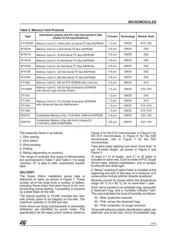
Memory Micromodules
General Information for D1, D2 and C Packaging
s
Micromodules were developed specifically for
embedding in Smartcards and Memory Cards
The Micromodule provides:
鈥?Support for the chip
鈥?Electrical contacts
鈥?Suitable embedding interface for gluing the
module to the plastic package
potting side
contact side
s
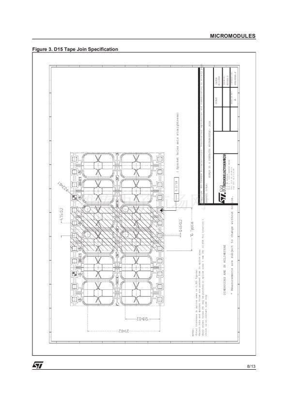
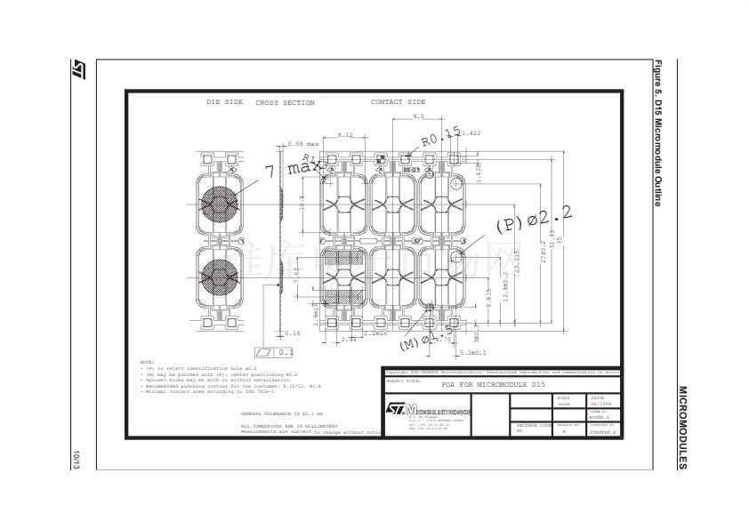
D15
s
Physical dimensions and contact positions
compliant to the ISO 7816 standard
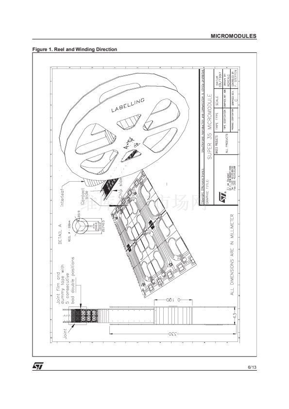
Micromodules delivered as a continuous Super
35 mm tape. (This differs from the standard
35 mm tape in the spacing distance between
the indexing holes.)
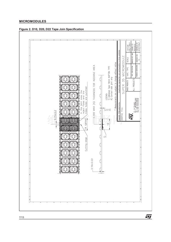
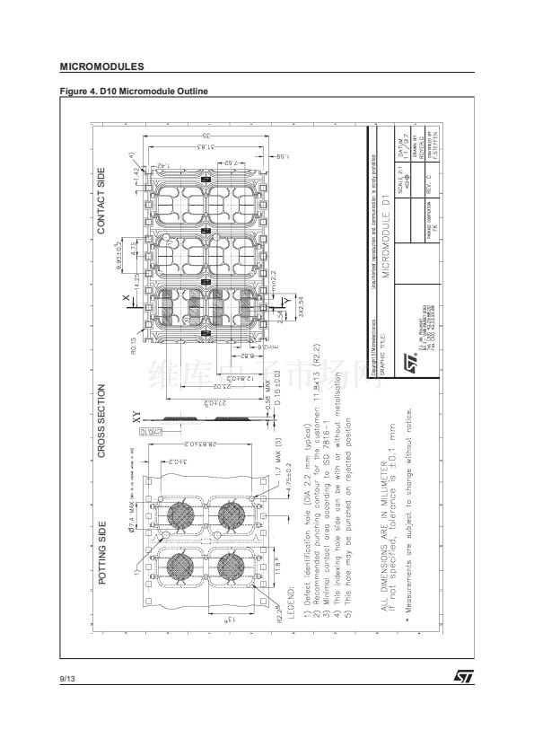
D10
D20
1
1
1
1
s
1
1
1
1
DESCRIPTION
Memory Cards consist of two main parts: the
plastic card, and the embedded Micromodule
(which, in turn, carries the silicon chip).
The plastic card is made of PVC, ABS or similar
material, and can be over-printed with graphics,
text, and magnetic strips. The Micromodule is
embedded in a cavity in the plastic card.
The Micromodules are mounted on Super 35 mm
metallized epoxy tape, and are delivered on reels.
These contain all of the chips from a number of
wafers, including those chips that were found to be
non-functioning during testing. Traceability is
ensured by a label fixed on the reel.
D22
C30
C20
Table 1. Memory Card and Memory Tag Integrated Circuits
Modul e
D10
D15
D20
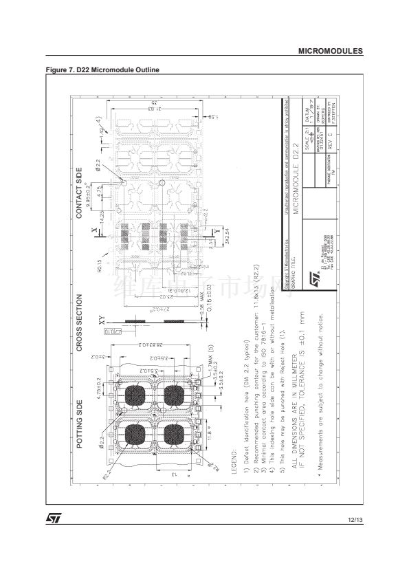
D22
C30
C20
Please see the data briefing sheets of these products for example illustrations of these
micromodules
ST1200, ST1305B, ST1331, ST1333, ST1335, ST1336, ST1353, ST1355
ST14C02, ST1305B, ST1335, ST1336, ST1355
ST14C02, M14C04, M14C16, M14C32
M14C64, M14128, M14256
M35101, M35102
M35101, M35102
December 1999
1/13


 1
1
 2
2
 3
3
 4
4
 5
5
 6
6
 7
7
 8
8
 9
9
 10
10
 11
11
 12
12
 13
13
