鈥?/div>
Off (鈥淗鈥?
Fixed at low (鈥淟鈥?
(Default setting)
Pulse Mode
*
1
2Hz (Duty cycle of 50%)
Pulse Mode
*
1
1Hz (Duty cycle of 50%)
Level Mode
*
2
Once per 1 second (Synchronized with second counter increment)
Level Mode
*
2
Once per minute (at 00 seconds of every minute)
Level Mode
*
2
Once per hour (at 00 minutes and 00 seconds of every hour)
Level Mode
*
2
Once per month (at 00 hours, 00 minutes, and 00 seconds of first day of every month)
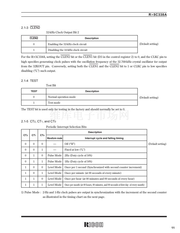
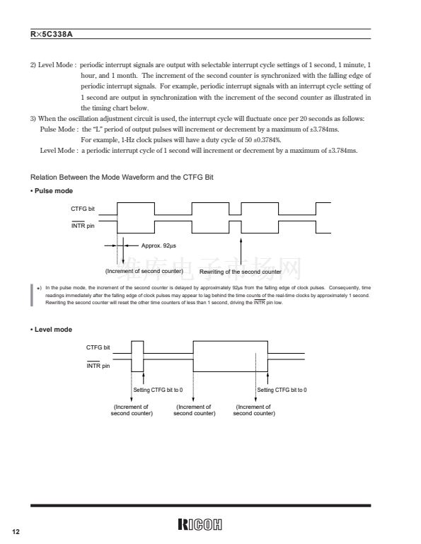
1) Pulse Mode : 2-Hz and 1-Hz clock pulses are output in synchronization with the increment of the second counter
as illustrated in the timing chart on the next page.
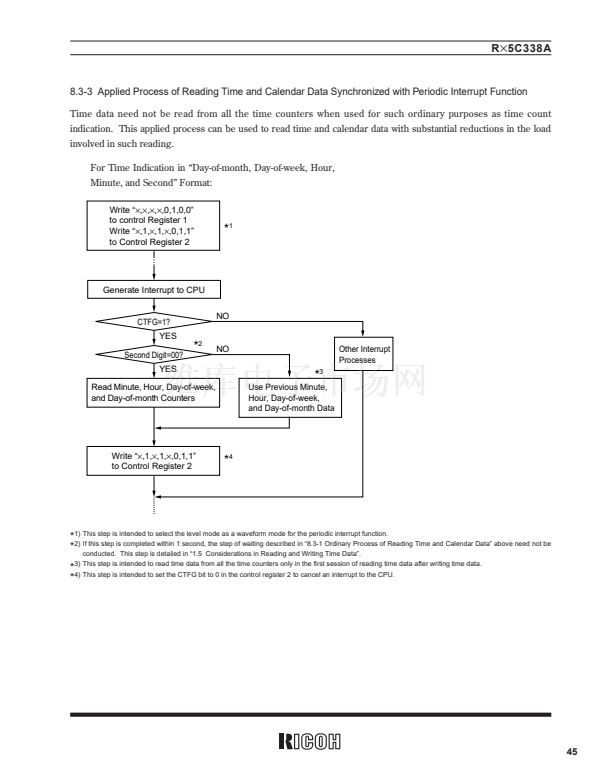
2) Level Mode : periodic interrupt signals are output with selectable interrupt cycle settings of 1 second, 1 minute, 1
hour, and 1 month. The increment of the second counter is synchronized with the falling edge of
periodic interrupt signals. For example, periodic interrupt signals with an interrupt cycle setting of
1 second are output in synchronization with the increment of the second counter as illustrated in
the timing chart on the next page.
3) When the oscillation adjustment circuit is used, the interrupt cycle will fluctuate once per 20 seconds as follows:
Pulse Mode : the 鈥淟鈥?period of output pulses will increment or decrement by a maximum of 鹵3.784ms.
For example, 1-Hz clock pulses will have a duty cycle of 50 鹵0.3784%.
Level Mode : a periodic interrupt cycle of 1 second will increment or decrement by a maximum of 鹵3.784ms.
36


 1
1
 2
2
 3
3
 4
4
 5
5
 6
6
 7
7
 8
8
 9
9
 10
10
 11
11
 12
12
 13
13
 14
14
 15
15
 16
16
 17
17
 18
18
 19
19
 20
20
 21
21
 22
22
 23
23
 24
24
 25
25
 26
26
 27
27
 28
28
 29
29
 30
30
 31
31
 32
32
 33
33
 34
34
 35
35
 36
36
 37
37
 38
38
 39
39
 40
40
 41
41
 42
42
 43
43
 44
44
 45
45
 46
46
 47
47
 48
48
 49
49
 50
50
 51
51
 52
52
