鈥?/div>
0
0
D6
WW
6
WW
6
D5
WW
5
WW
5
D4
WW
4
WW
4
D3
WW
3
WW
3
D2
WW
2
WW
2
D1
WW
1
WW
1
D0
WW
0
WW
0
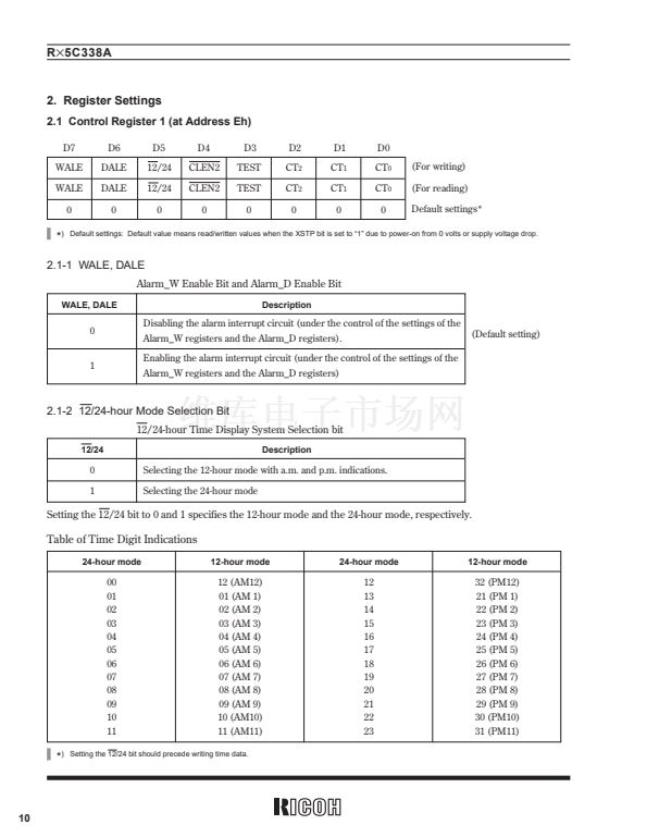
(For writing)
(For reading)
Default settings*
Indefinite Indefinite Indefinite Indefinite Indefinite Indefinite Indefinite
*
)
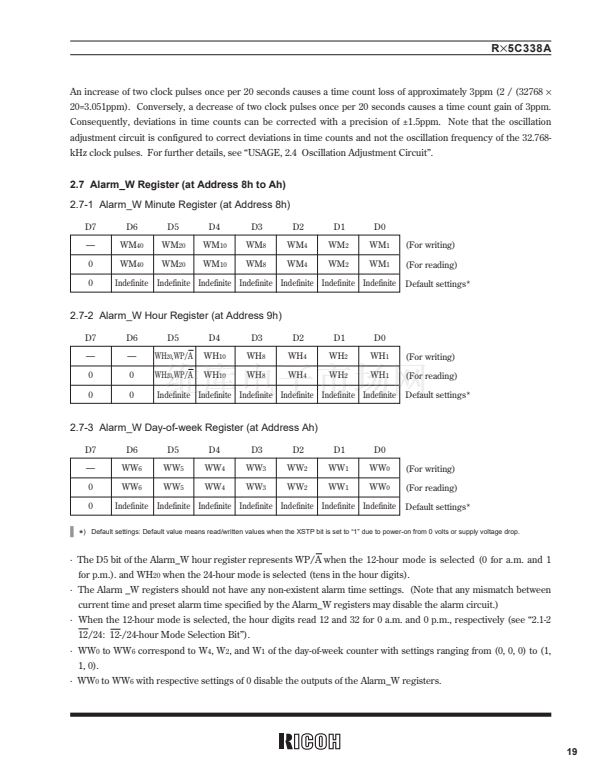
Default settings: Default value means read/written values when the XSTP bit is set to 鈥?鈥?due to power-on from 0 volts or supply voltage drop.
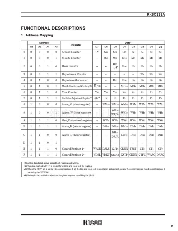
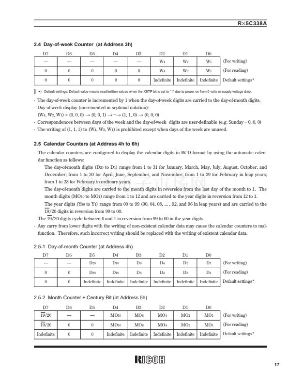
路 The D5 bit of the Alarm_W hour register represents WP/A when the 12-hour mode is selected (0 for a.m. and 1
for p.m.). and WH
20
when the 24-hour mode is selected (tens in the hour digits).
路 The Alarm _W registers should not have any non-existent alarm time settings. (Note that any mismatch between
current time and preset alarm time specified by the Alarm_W registers may disable the alarm circuit.)
路 When the 12-hour mode is selected, the hour digits read 12 and 32 for 0 a.m. and 0 p.m., respectively (see 鈥?.1-2
12/24: 12-/24-hour Mode Selection Bit鈥?.
路 WW
0
to WW
6
correspond to W
4
, W
2
, and W
1
of the day-of-week counter with settings ranging from (0, 0, 0) to (1,
1, 0).
路 WW
0
to WW
6
with respective settings of 0 disable the outputs of the Alarm_W registers.
19


 1
1
 2
2
 3
3
 4
4
 5
5
 6
6
 7
7
 8
8
 9
9
 10
10
 11
11
 12
12
 13
13
 14
14
 15
15
 16
16
 17
17
 18
18
 19
19
 20
20
 21
21
 22
22
 23
23
 24
24
 25
25
 26
26
 27
27
 28
28
 29
29
 30
30
 31
31
 32
32
 33
33
 34
34
 35
35
 36
36
 37
37
 38
38
 39
39
 40
40
 41
41
 42
42
 43
43
 44
44
 45
45
 46
46
 47
47
 48
48
 49
49
 50
50
 51
51
 52
52
