R
脳
5C338A
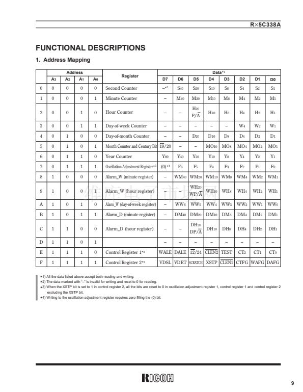
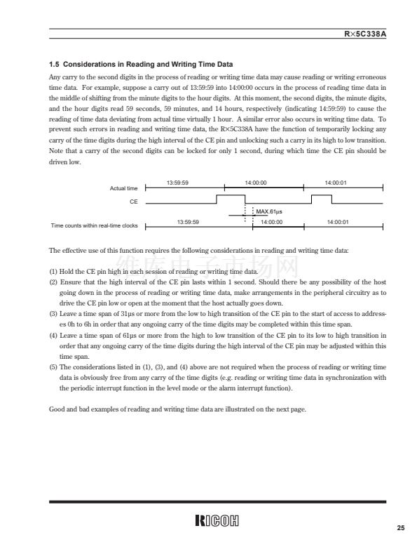
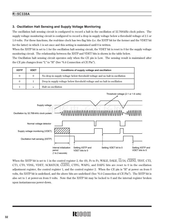
2. Register Settings
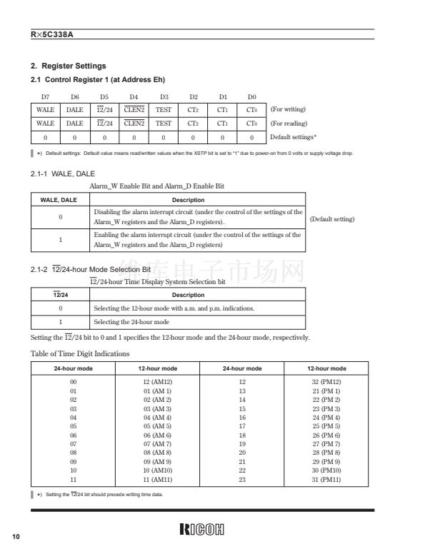
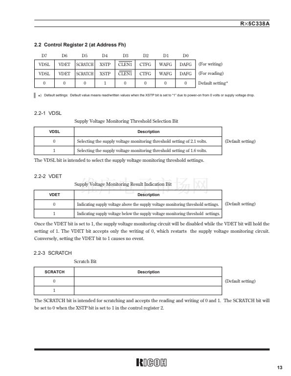
2.1 Control Register 1 (at Address Eh)
D7
WALE
WALE
0
D6
DALE
DALE
0
D5
12/24
12/24
0
D4
CLEN2
CLEN2
0
D3
TEST
TEST
0
D2
CT
2
CT
2
0
D1
CT
1
CT
1
0
D0
CT
0
CT
0
0
(For writing)
(For reading)
Default settings*
*
)
Default settings: Default value means read/written values when the XSTP bit is set to 鈥?鈥?due to power-on from 0 volts or supply voltage drop.
2.1-1 WALE, DALE
Alarm_W Enable Bit and Alarm_D Enable Bit
WALE, DALE
Description
0
Disabling the alarm interrupt circuit (under the control of the settings of the
Alarm_W registers and the Alarm_D registers).
Enabling the alarm interrupt circuit (under the control of the settings of the
Alarm_W registers and the Alarm_D registers)
(Default setting)
1
2.1-2 12/24-hour Mode Selection Bit
12/24-hour Time Display System Selection bit
12/24
Description
0
1
Selecting the 12-hour mode with a.m. and p.m. indications.
Selecting the 24-hour mode
Setting the 12/24 bit to 0 and 1 specifies the 12-hour mode and the 24-hour mode, respectively.
Table of Time Digit Indications
24-hour mode
12-hour mode
24-hour mode
12-hour mode
00
01
02
03
04
05
06
07
08
09
10
11
12 (AM12)
01 (AM 1)
02 (AM 2)
03 (AM 3)
04 (AM 4)
05 (AM 5)
06 (AM 6)
07 (AM 7)
08 (AM 8)
09 (AM 9)
10 (AM10)
11 (AM11)
12
13
14
15
16
17
18
19
20
21
22
23
32 (PM12)
21 (PM 1)
22 (PM 2)
23 (PM 3)
24 (PM 4)
25 (PM 5)
26 (PM 6)
27 (PM 7)
28 (PM 8)
29 (PM 9)
30 (PM10)
31 (PM11)
*
)
Setting the 12/24 bit should precede writing time data.
10


 1
1
 2
2
 3
3
 4
4
 5
5
 6
6
 7
7
 8
8
 9
9
 10
10
 11
11
 12
12
 13
13
 14
14
 15
15
 16
16
 17
17
 18
18
 19
19
 20
20
 21
21
 22
22
 23
23
 24
24
 25
25
 26
26
 27
27
 28
28
 29
29
 30
30
 31
31
 32
32
 33
33
 34
34
 35
35
 36
36
 37
37
 38
38
 39
39
 40
40
 41
41
 42
42
 43
43
 44
44
 45
45
 46
46
 47
47
 48
48
 49
49
 50
50
 51
51
 52
52
