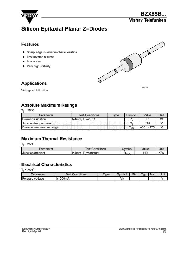
BZX85B...
Vishay Telefunken
Characteristics
(T
j
= 25
_
C unless otherwise specified)
2.0
P
tot
鈥?Total Power Dissipation ( W )
C
D
鈥?Diode Capacitance ( pF )
1000
1.6
100
V
R
= 0V
V
R
= 2V
V
R
= 5V
V
R
= 20V
V
R
= 30V
1.2
l=4mm
0.8
l=20mm
0.4
0
鈥?0
l=10mm
10
1
0
50
100
150
200
95 9616
f = 1 MHz
T
amb
= 25擄C
0
10
20
30
40
50
60
95 9612
T
amb
鈥?Ambient Temperature (
擄C
)
V
Z
鈥?Z-Voltage ( V )
Figure 1. Total Power Dissipation vs. Ambient Tempera-
ture
R
thJA
鈥?Therm. Resist. Junction / Ambient ( K/W )
r
Z
鈥?Differential Z-Resistance (
W
)
250
Figure 3. Diode Capacitance vs. Z鈥揤oltage
1000
I
Z
=1mA
100
2mA
5mA
10mA
20mA
10
200
150
l
100
50
0
0
5
10
15
T
L
=constant
20
25
30
l
1
1
95 9615
10
V
Z
鈥?Z-Voltage ( V )
100
95 9613
l 鈥?Lead Length ( mm )
Figure 4. Differential Z鈥揜esistance vs. Z鈥揤oltage
Z
thp
鈥?Thermal Resistance for Pulse Cond. (K/W)
Figure 2. Thermal Resistance vs. Lead Length
1000
t
p
/T=0.01
t
p
/T=0.1
100
t
p
/T=0.5
t
p
/T=0.2
10
Single Pulse
i
ZM
=(鈥揤
Z
+(V
Z2
+4r
zj
1
10
鈥?
10
0
10
1
t
p
鈥?Pulse Length ( ms )
10
2
t
p
/T=0.05
t
p
/T=0.02
D
T=T
jmax
鈥揟
amb
R
thJA
=110K/W
�
D
T/Z
thp
)
1/2
)/(2r
zj
)
10
3
95 9614
Figure 5. Thermal Response
Document Number 85607
Rev. 3, 01-Apr-99
www.vishay.de
鈥?/div>
FaxBack +1-408-970-5600
3 (5)


 1
1
 2
2
 3
3
 4
4
 5
5
