Philips Semiconductors
Product speci鏗乧ation
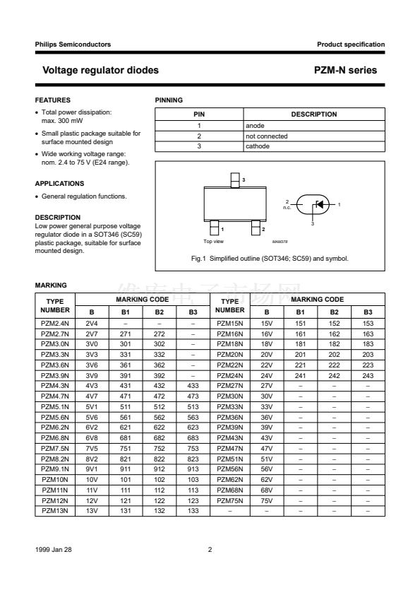
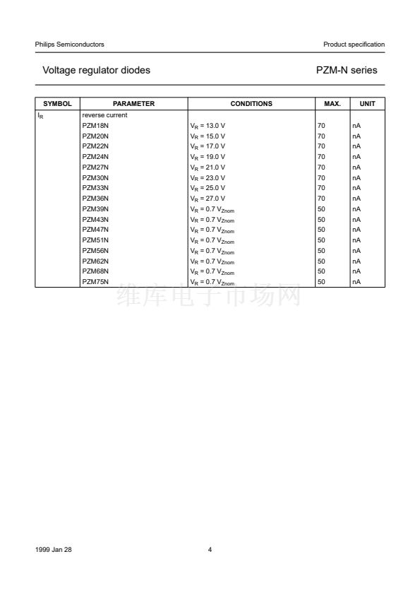
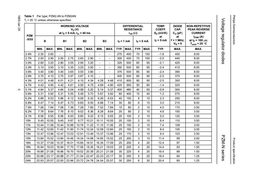
Voltage regulator diodes
LIMITING VALUES
In accordance with the Absolute Maximum Rating System (IEC 134).
SYMBOL
I
F
I
ZSM
P
tot
T
stg
T
j
PARAMETER
continuous forward current
non-repetitive peak current
total power dissipation
storage temperature
operating junction temperature
t
p
= 100
碌s;
square wave;
T
amb
= 25
擄C
prior to surge
T
amb
= 25
擄C
CONDITIONS
鈭?/div>
MIN.
PZM-N series
MAX.
250
UNIT
mA
see Tables 1 and 2
鈭?/div>
鈭?5
鈭?/div>
300
+150
150
mW
擄C
擄C
THERMAL CHARACTERISTICS
SYMBOL
R
th j-s
PARAMETER
CONDITIONS
VALUE
300
UNIT
K/W
thermal resistance from junction to soldering point T
s
= 60
擄C
ELECTRICAL CHARACTERISTICS
T
j
= 25
擄C
unless otherwise speci鏗乪d.
SYMBOL
V
F
I
R
PARAMETER
forward voltage
reverse current
PZM2.4N
PZM2.7N
PZM3.0N
PZM3.3N
PZM3.6N
PZM3.9N
PZM4.3N
PZM4.7N
PZM5.1N
PZM5.6N
PZM6.2N
PZM6.8N
PZM7.5N
PZM8.2N
PZM9.1N
PZM10N
PZM11N
PZM12N
PZM13N
PZM15N
PZM16N
1999 Jan 28
V
R
= 1 V
V
R
= 1 V
V
R
= 1 V
V
R
= 1 V
V
R
= 1 V
V
R
= 1 V
V
R
= 1 V
V
R
= 1 V
V
R
= 1.5 V
V
R
= 2.5 V
V
R
= 3.0 V
V
R
= 3.5 V
V
R
= 4.0 V
V
R
= 5.0 V
V
R
= 6.0 V
V
R
= 7.0 V
V
R
= 8.0 V
V
R
= 9.0 V
V
R
= 10.0 V
V
R
= 11.0 V
V
R
= 12.0 V
3
50
20
10
5
5
3
3
3
3
2
2
2
1
700
500
200
100
100
100
70
70
碌A(chǔ)
碌A(chǔ)
碌A(chǔ)
碌A(chǔ)
碌A(chǔ)
碌A(chǔ)
碌A(chǔ)
碌A(chǔ)
碌A(chǔ)
碌A(chǔ)
碌A(chǔ)
碌A(chǔ)
碌A(chǔ)
nA
nA
nA
nA
nA
nA
nA
nA
CONDITIONS
I
F
= 10 mA; see Fig.2
I
F
= 100 mA; see Fig.2
MAX.
0.9
1.1
V
V
UNIT


 1
1
 2
2
 3
3
 4
4
 5
5
 6
6
 7
7
 8
8
 9
9
 10
10
 11
11
 12
12
