Philips Semiconductors
Product speci鏗乧ation
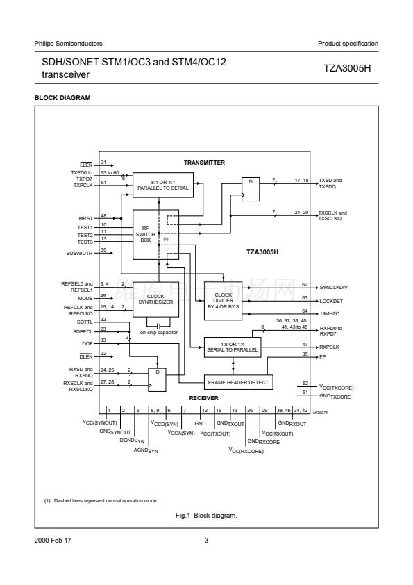
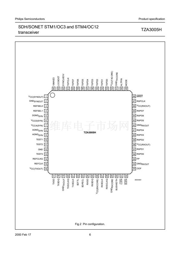
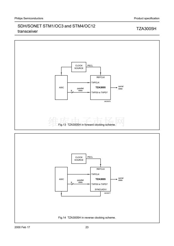
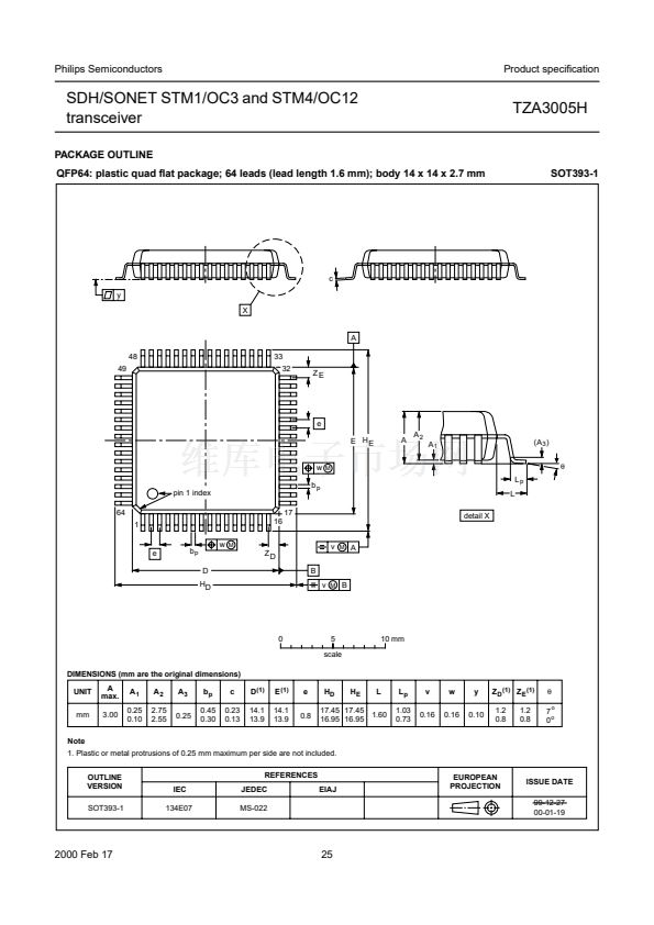
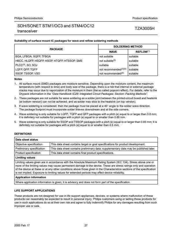
SDH/SONET STM1/OC3 and STM4/OC12
transceiver
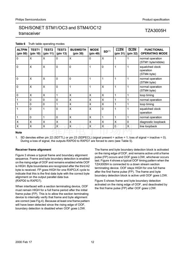
Table 6
Truth table operating modes
BUSWIDTH
(pin 30)
X
0
MODE
(pin 49)
0
1
SD
(1)
X
0
LLEN
DLEN
(pin 31) (pin 32)
1
1
1
1
TZA3005H
ALTPIN TEST1 TEST2 TEST3
(pin 50) (pin 10) (pin 11) (pin 13)
0
0
X
X
X
X
0
0
FUNCTIONAL
OPERATING MODE
normal operation
(STM1 byte/nibble)
squelched clock
operation
(STM4 byte)
normal operation
(STM4 byte)
normal operation
(STM4 byte)
loop timing
normal operation
loop timing
squelched clock
operation
normal operation
diagnostic loopback
line loopback
0
0
0
1
1
1
1
X
X
Note
X
X
X
0
0
0
0
X
X
X
X
X
0
0
1
1
X
X
0
0
1
0
1
0
0
X
X
0
1
X
X
X
X
X
X
X
1
1
X
X
X
X
X
X
X
1
X
X
X
X
0
1
X
X
1
1
1
1
1
1
1
X
0
1
1
1
1
1
1
1
0
X
1. SD denotes either pin 22 (SDTTL) or pin 23 (SDPECL) (signal present = active = 1; loss of signal = inactive = 0).
During a loss of signal, the outputs RXPD0 to RXPD7 are forced to zero (see Table 5).
Receiver frame alignment
Figure 3 shows a typical frame and boundary alignment
sequence. Frame and byte boundary detection is enabled
on the rising edge of OOF and remains enabled while OOF
is HIGH. Byte boundaries are recognized after the third A2
byte is received. FP goes HIGH for one RXPCLK cycle to
indicate that this is the first data byte with the correct byte
alignment on the output parallel data bus
(RXPD0 to RXPD7).
When interfaced with a section terminating device, OOF
must remain HIGH for a full frame period after the initial
frame pulse (FP). This is to allow the section terminating
device to internally verify that frame and byte alignment
are correct (see Fig.4). Because at least one frame pattern
will have been detected since the rising edge of OOF,
boundary detection is disabled when OOF goes LOW.
The frame and byte boundary detection block is activated
on the rising edge of OOF, and remains active until a frame
pulse (FP) occurs and OOF goes LOW, whichever occurs
last. Figure 4 shows a typical OOF timing pattern when the
TZA3005H is connected to a down stream section
terminating device. OOF stays HIGH for one full frame
after the first frame pulse (FP). The frame and byte
boundary detection block is active until OOF goes LOW.
Figure 5 shows frame and byte boundary detection
activated on the rising edge of OOF, and deactivated by
the first frame pulse (FP) after OOF goes LOW.
2000 Feb 17
12


 1
1
 2
2
 3
3
 4
4
 5
5
 6
6
 7
7
 8
8
 9
9
 10
10
 11
11
 12
12
 13
13
 14
14
 15
15
 16
16
 17
17
 18
18
 19
19
 20
20
 21
21
 22
22
 23
23
 24
24
 25
25
 26
26
 27
27
 28
28
