P10C68/P11C68
P10C68 RECALL CYCLE 1 : NE (BAR) CONTROLLED
(See note 16)
Symbol
Standard
t
NLQX
t
NLNH
t
GLNL
t
WHNL
t
ELNL
t
NLQZ
Alternative
t
RECALL
t
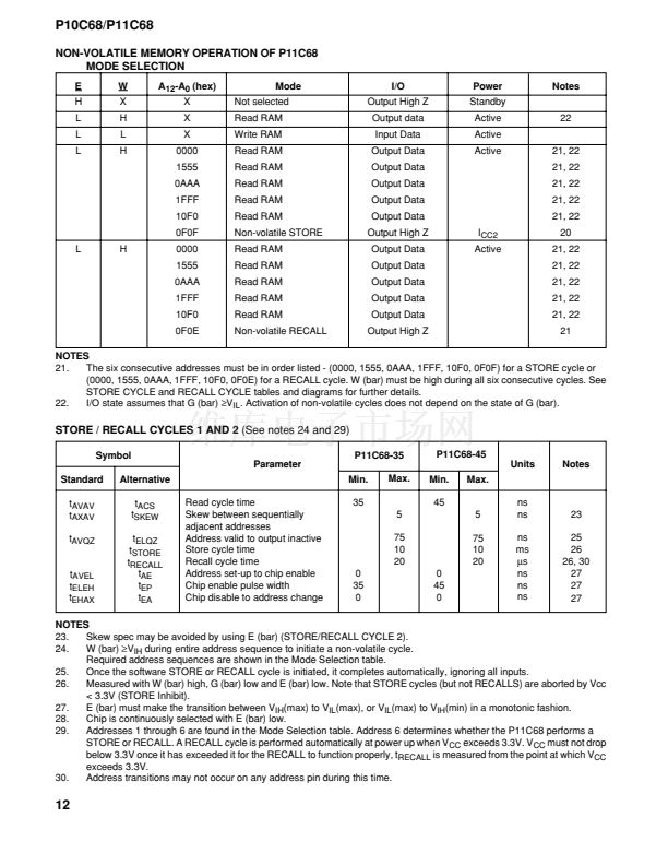
RC
Recall cycle time
Recall initiation cycle time
Output enable set-up
Write enable set-up
Chip enable set-up
NE (bar) fall to output inactive
P10C68-35
Parameter
Min.
Max.
20
25
0
0
0
25
25
0
0
0
25
Min.
Max.
20
碌s
碌s
ns
ns
ns
ns
19
20
P10C68-45
Units
Notes
P10C68 RECALL CYCLE 2 : E (BAR) CONTROLLED
(See note 16)
Symbol
Standard
t
ELQX2
t
ELNH
t
NLEL
t
GLEL
t
WHEL
Alternative
t
RECALL
t
RC
Recall cycle time
Recall initiation cycle time
NE (bar) set-up
Output enable set-up
Write enable set-up
P10C68-35
Parameter
Min.
Max.
20
25
0
0
0
25
0
0
0
P10C68-45
Min.
Max.
20
碌s
ns
ns
ns
ns
19
20
Units
Notes
P10C68 RECALL CYCLE 3 : G (BAR) CONTROLLED
(See note 16)
Symbol
Standard
t
GLQX2
t
GLNH
t
NLGL
t
WHGL
t
ELGL
Alternative
t
RECALL
t
RC
Recall cycle time
Recall initiation cycle time
NE (bar) set-up
Write enable set-up
Chip enable set-up
P10C68-35
Parameter
Min.
Max.
20
25
0
0
0
25
0
0
0
P10C68-45
Min.
Max.
20
碌s
ns
ns
ns
ns
19
20
Units
Notes
NOTES
19.
Measured with W (bar) and NE (bar) both returned high, and G (bar) returned low. Address transitions may not occur on
any address pin during this time.
20.
Once t
RC
has been satisfied by NE (bar), G (bar), W (bar) and E (bar) the RECALL cycle is completed automatically. Any
of NE (bar), G (bar) or E (bar) may be used to terminate the RECALL initiation cycle.
10


 1
1
 2
2
 3
3
 4
4
 5
5
 6
6
 7
7
 8
8
 9
9
 10
10
 11
11
 12
12
 13
13
 14
14
 15
15
 16
16
 17
17
