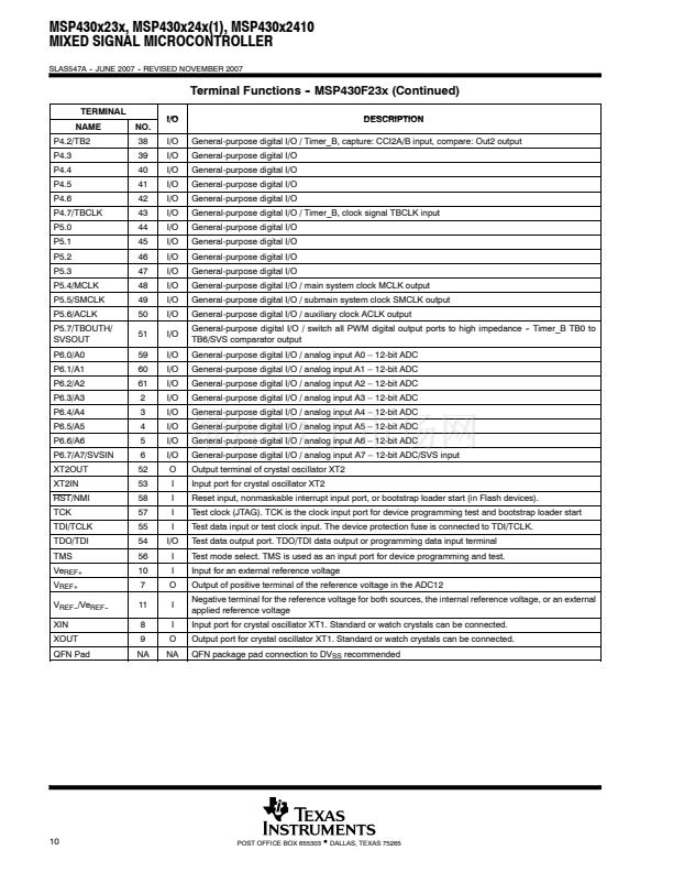
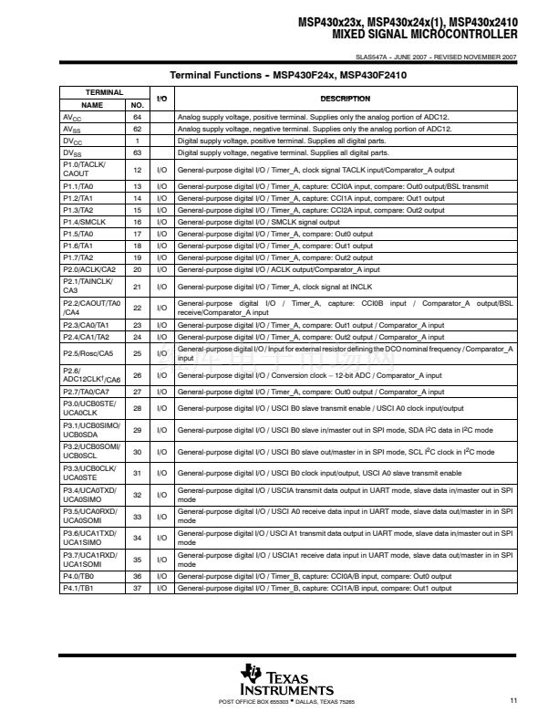
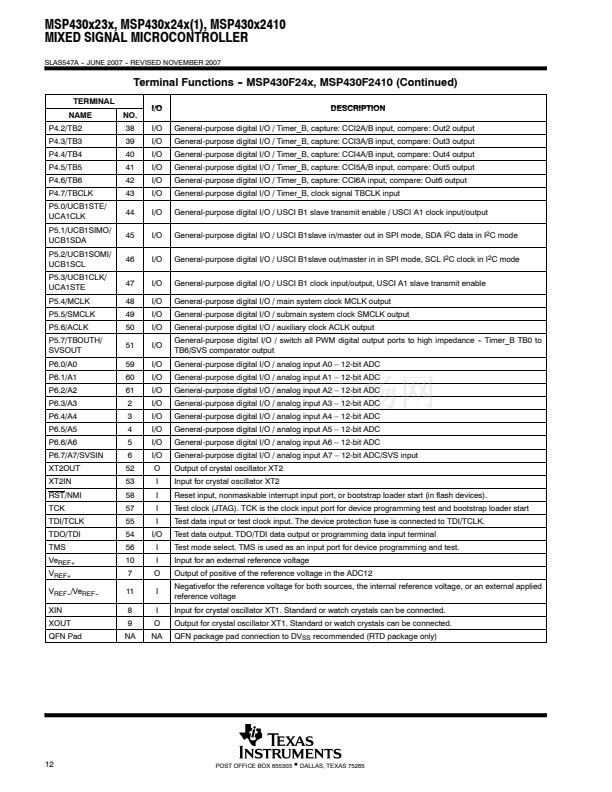
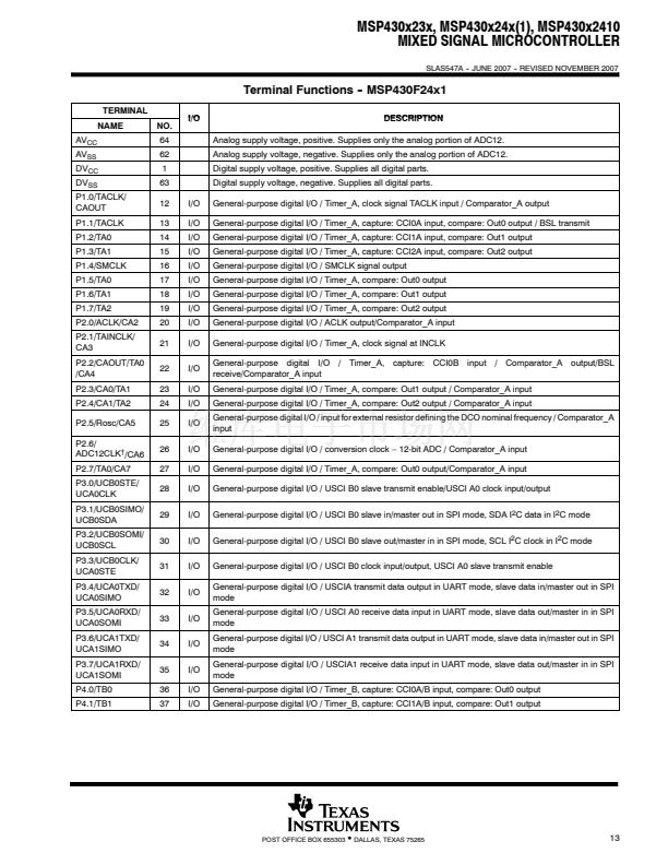
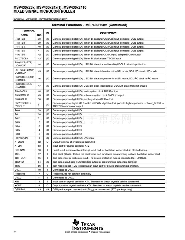
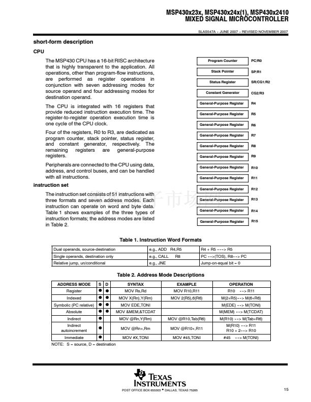
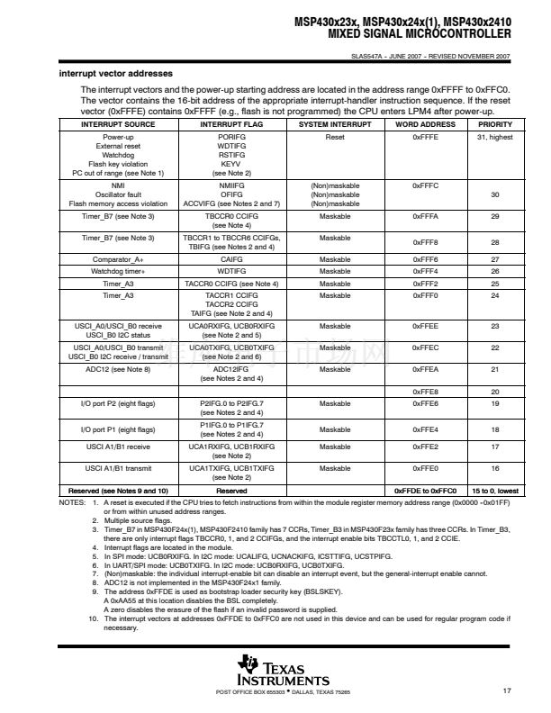
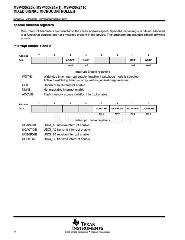
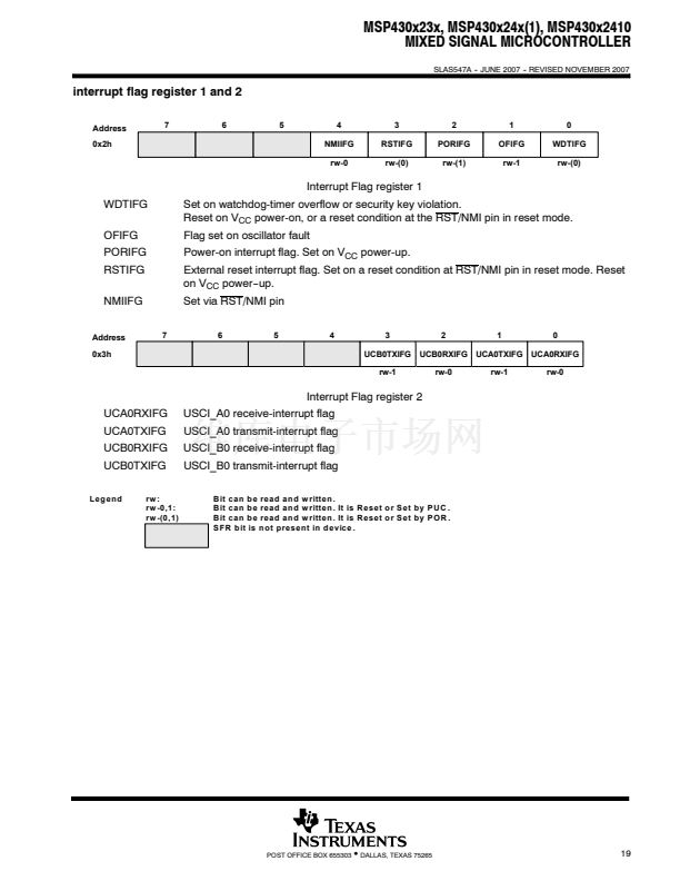
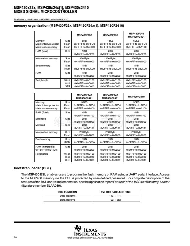
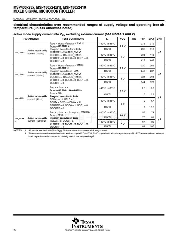
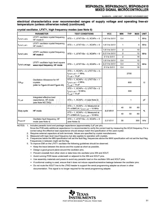
MSP430x23x, MSP430x24x(1), MSP430x2410
MIXED SIGNAL MICROCONTROLLER
SLAS547A -- JUNE 2007 -- REVISED NOVEMBER 2007
electrical characteristics over recommended ranges of supply voltage and operating free-air
temperature (unless otherwise noted) (continued)
Schmitt-trigger inputs - ports P1, P2, P3, P4, P5, P6, RST/NMI, JTAG, XIN, and XT2IN (see Note 6)
-
PARAMETER
V
IT+
Positive going
Positive-going input threshold voltage
TEST CONDITIONS
VCC
2.2 V
3V
V
IT--
Negative going
Negative-going input threshold voltage
2.2 V
3V
V
hys
R
Pull
C
I
Input voltage hysteresis (V
IT+
-- V
IT--
)
Pullup/pulldown resistor
Input Capacitance
Pullup: V
IN
= V
SS
,
Pulldown: V
IN
= V
CC
V
IN
= V
SS
or V
CC
2.2 V
3V
MIN
0.45 V
CC
1.0
1.35
0.25 V
CC
0.55
0.75
0.2
0.3
20
35
5
TYP
MAX
0.75 V
CC
1.65
2.25
0.55 V
CC
1.2
1.65
1.0
1.0
50
V
k惟
pF
V
V
UNIT
NOTE 6. XIN and XT2IN only in bypass mode
inputs - ports P1 and P2
-
PARAMETER
t
int
External interrupt timing
TEST CONDITIONS
Port P1, P2: P1.x to P2.x, external
trigger pulse width to set the interrupt
flag (see Note 1)
TA0, TA1, TA2
TB0, TB1, TB2, TB3, TB4, TB5, TB6
TACLK, TBCLK,
TACLK TBCLK INCLK: t
(H)
= t
(L)
SMCLK or ACLK signal selected
VCC
2.2 V/3 V
2.2 V
3V
2.2 V
3V
2.2 V
3V
MIN
20
62
50
8
10
8
10
MAX
UNIT
ns
t
cap
f
TAext
f
TBext
f
TAint
f
TBint
Timer_A, Timer_B
Timer A Timer B capture timing
Timer_A, Timer_B clock frequency externally
applied to pin
Timer_A, Timer_B
Timer A Timer B clock frequency
ns
MHz
MHz
NOTE 1. The external signal sets the interrupt flag every time the minimum t
(int)
parameters are met. It may be set even with trigger signals shorter
than t
(int)
.
leakage current - ports P1, P2, P3, P4, P5, and P6 (see Note 1 and 2)
-
PARAMETER
I
lkg(Px.x)
High impedance leakage current
TEST CONDITIONS
See Notes 1 and 2
VCC
2.2 V/3 V
MIN
MAX
鹵50
UNIT
nA
NOTES: 1. The leakage current is measured with V
SS
or V
CC
applied to the corresponding pin(s), unless otherwise noted.
2. The leakage of digital port pins is measured individually. The port pin is selected for input and the pullup/pull--down resistor is
disabled..
standard inputs - RST/NMI
-
PARAMETER
V
IL
V
IH
Low-level input voltage
High-level input voltage
TEST CONDITIONS
VCC
2.2 V/3 V
2.2 V/3 V
MIN
V
SS
0.8 V
CC
MAX
V
SS
+ 0.6
V
CC
UNIT
V
V
36
POST OFFICE BOX 655303
鈥?/div>
DALLAS, TEXAS 75265


 1
1
 2
2
 3
3
 4
4
 5
5
 6
6
 7
7
 8
8
 9
9
 10
10
 11
11
 12
12
 13
13
 14
14
 15
15
 16
16
 17
17
 18
18
 19
19
 20
20
 21
21
 22
22
 23
23
 24
24
 25
25
 26
26
 27
27
 28
28
 29
29
 30
30
 31
31
 32
32
 33
33
 34
34
 35
35
 36
36
 37
37
 38
38
 39
39
 40
40
 41
41
 42
42
 43
43
 44
44
 45
45
 46
46
 47
47
 48
48
 49
49
 50
50
 51
51
 52
52
 53
53
 54
54
 55
55
 56
56
 57
57
 58
58
 59
59
 60
60
 61
61
 62
62
 63
63
 64
64
 65
65
 66
66
 67
67
 68
68
 69
69
 70
70
 71
71
 72
72
 73
73
 74
74
 75
75
 76
76
 77
77
 78
78
 79
79
 80
80
 81
81
 82
82
 83
83
 84
84
 85
85
 86
86
 87
87
 88
88
 89
89
 90
90
 91
91
