MIC5014/5015
Micrel
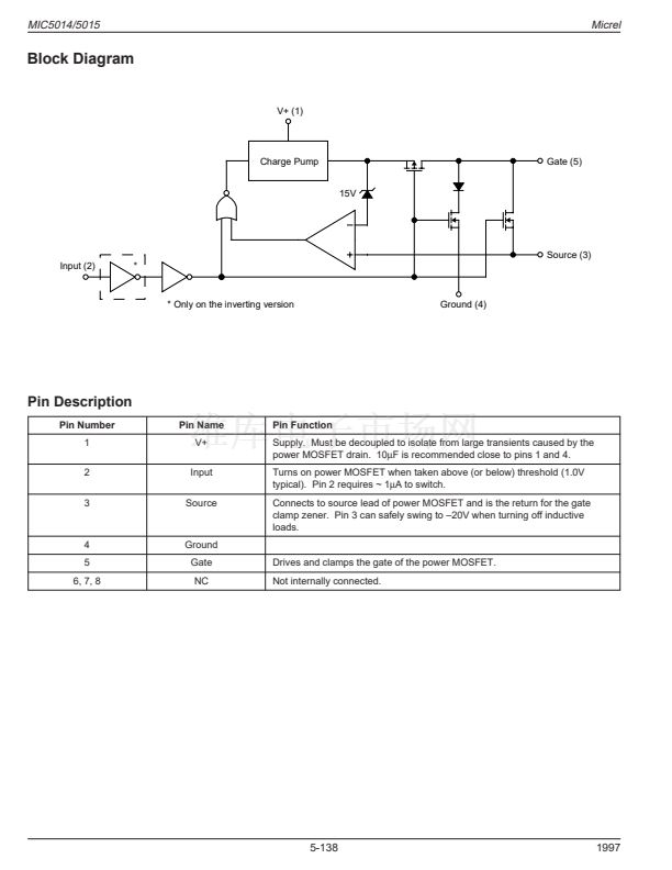
Block Diagram
V+ (1)
Charge Pump
Gate (5)
15V
Source (3)
Input (2)
*
* Only on the inverting version
Ground (4)
Pin Description
Pin Number
1
2
3
Pin Name
V+
Input
Source
Pin Function
Supply. Must be decoupled to isolate from large transients caused by the
power MOSFET drain. 10碌F is recommended close to pins 1 and 4.
Turns on power MOSFET when taken above (or below) threshold (1.0V
typical). Pin 2 requires ~ 1碌A to switch.
Connects to source lead of power MOSFET and is the return for the gate
clamp zener. Pin 3 can safely swing to 鈥?0V when turning off inductive
loads.
4
5
6, 7, 8
Ground
Gate
NC
Drives and clamps the gate of the power MOSFET.
Not internally connected.
5-138
1997


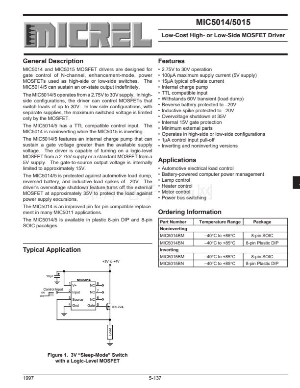 1
1
 2
2
 3
3
 4
4
 5
5
 6
6
 7
7
 8
8
 9
9
