PWM.
鈮?/div>
0.7mA
+
-
1
2
Error Amp
1
1
3
Feedback/PWM
Comparator Input
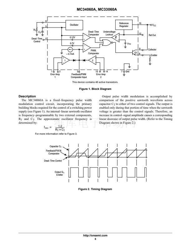
This device contains 46 active transistors.
Figure 1. Block Diagram
Description
The MC34060A is a fixed鈥揻requency pulse width
modulation control circuit, incorporating the primary
building blocks required for the control of a switching power
supply (see Figure 1). An internal鈥搇inear sawtooth oscillator
is frequency鈥損rogrammable by two external components,
R
T
and C
T
. The approximate oscillator frequency is
determined by:
f
osc
^
1.2
R
T
鈥?/div>
C
T
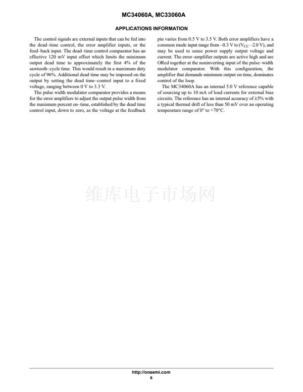
Output pulse width modulation is accomplished by
comparison of the positive sawtooth waveform across
capacitor C
T
to either of two control signals. The output is
enabled only during that portion of time when the sawtooth
voltage is greater than the control signals. Therefore, an
increase in control鈥搒ignal amplitude causes a corresponding
linear decrease of output pulse width. (Refer to the Timing
Diagram shown in Figure 2.)
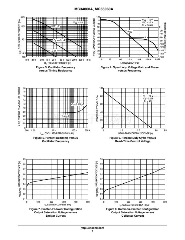
For more information refer to Figure 3.
Capacitor C
T
Feedback/P.W.M.
Comparator
Dead-Time Control
Output Q
1
,
Emitter
Figure 2. Timing Diagram
http://onsemi.com
5


 1
1
 2
2
 3
3
 4
4
 5
5
 6
6
 7
7
 8
8
 9
9
 10
10
 11
11
 12
12
 13
13
 14
14
 15
15
 16
16
