LP3907
I
2
C Compatible Serial Interface
I
2
C SIGNALS
The LP3907 features an I
2
C compatible serial interface, using
two dedicated pins: SCL and SDA for I
2
C clock and data re-
spectively. Both signals need a pull-up resistor according to
the I
2
C specification. The LP3907 interface is an I
2
C slave that
is clocked by the incoming SCL clock.
Signal timing specifications are according to the I
2
C bus spec-
ification. The maximum bit rate is 400kbit/s. See I
2
C specifi-
cation from Philips for further details.
I
2
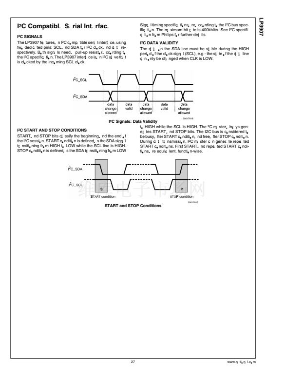
C DATA VALIDITY
The data on the SDA line must be stable during the HIGH
period of the clock signal (SCL), e.g.- the state of the data line
can only be changed when CLK is LOW.
30017816
I
2
C Signals: Data Validity
to HIGH while the SCL is HIGH. The
2
C master always gen-
I
2
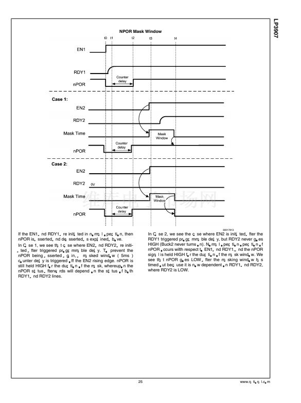
C START AND STOP CONDITIONS
erates START and STOP bits. The I2C bus is considered to
START and STOP bits classify the beginning and the end of
be busy after START condition and free after STOP condition.
the I
2
C session. START condition is defined as the SDA signal
During data transmission, I
2
C master can generate repeated
transitioning from HIGH to LOW while the SCL line is HIGH.
START conditions. First START and repeated START condi-
STOP condition is defined as the SDA transitioning from LOW
tions are equivalent, function-wise.
30017817
START and STOP Conditions
27
www.national.com


 1
1
 2
2
 3
3
 4
4
 5
5
 6
6
 7
7
 8
8
 9
9
 10
10
 11
11
 12
12
 13
13
 14
14
 15
15
 16
16
 17
17
 18
18
 19
19
 20
20
 21
21
 22
22
 23
23
 24
24
 25
25
 26
26
 27
27
 28
28
 29
29
 30
30
 31
31
 32
32
 33
33
 34
34
 35
35
 36
36
 37
37
 38
38
 39
39
 40
40
 41
41
 42
42
 43
43
 44
44
