LP3907
SW1, SW2: Synchronous Step-
Down Magnetic DC/DC Converters
FUNCTIONAL DESCRIPTION
The LP3907 incorporates two high-efficiency synchronous
switching buck regulators, SW1 and SW2, that deliver a con-
stant voltage from a single Li-Ion battery to the portable
system processors. Using a voltage mode architecture with
synchronous rectification, both bucks have the ability to de-
liver up to 1000mA and 600mA, respectively, depending on
the input voltage and output voltage (voltage head room), and
the inductor chosen (maximum current capability).
There are three modes of operation depending on the current
required - PWM, PFM, and shutdown. PWM mode handles
current loads of approximately 70mA or higher, delivering
voltage precision of +/-3% with 90% efficiency or better.
Lighter output current loads cause the device to automatically
switch into PFM for reduced current consumption (I
Q
= 15碌A(chǔ)
typ.) and a longer battery life. The Standby operating mode
turns off the device, offering the lowest current consumption.
PWM or PFM mode is selected automatically or PWM mode
can be forced through the setting of the buck control register.
Both SW1 and SW2 can operate up to a 100% duty cycle
(PMOS switch always on) for low drop out control of the output
voltage. In this way the output voltage will be controlled down
to the lowest possible input voltage.
Additional features include soft-start, under-voltage lock-out,
current overload protection, and thermal overload protection.
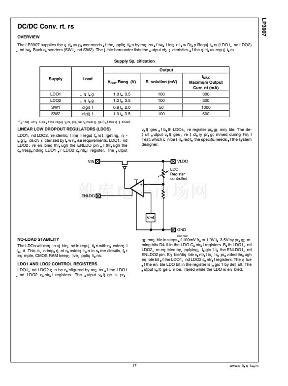
CIRCUIT OPERATION DESCRIPTION
A buck converter contains a control block, a switching PFET
connected between input and output, a synchronous rectify-
ing NFET connected between the output and ground
(BCKGND pin) and a feedback path. During the first portion
of each switching cycle, the control block turns on the internal
PFET switch. This allows current to flow from the input
through the inductor to the output filter capacitor and load. The
inductor limits the current to a ramp with a slope of
INTERNAL SYNCHRONOUS RECTIFICATION
While in PWM mode, the buck uses an internal NFET as a
synchronous rectifier to reduce rectifier forward voltage drop
and associated power loss. Synchronous rectification pro-
vides a significant improvement in efficiency whenever the
output voltage is relatively low compared to the voltage drop
across an ordinary rectifier diode.
CURRENT LIMITING
A current limit feature allows the converter to protect itself and
external components during overload conditions. PWM mode
implements current limiting using an internal comparator that
trips at 1.5A for Buck1 and at 1.0A for Buck2 (typ). If the output
is shorted to ground the device enters a timed current limit
mode where the NFET is turned on for a longer duration until
the inductor current falls below a low threshold, ensuring in-
ductor current has more time to decay, thereby preventing
runaway.
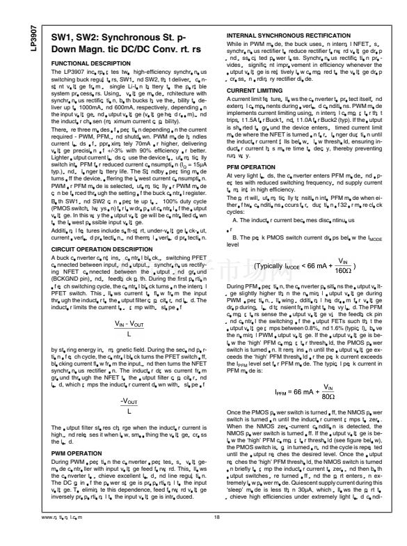
PFM OPERATION
At very light loads, the converter enters PFM mode and op-
erates with reduced switching frequency and supply current
to maintain high efficiency.
The part will automatically transition into PFM mode when ei-
ther of two conditions occurs for a duration of 32 or more clock
cycles:
A. The inductor current becomes discontinuous
or
B. The peak PMOS switch current drops below the I
MODE
level
by storing energy in a magnetic field. During the second por-
tion of each cycle, the control block turns the PFET switch off,
blocking current flow from the input, and then turns the NFET
synchronous rectifier on. The inductor draws current from
ground through the NFET to the output filter capacitor and
load, which ramps the inductor current down with a slope of
During PFM operation, the converter positions the output volt-
age slightly higher than the nominal output voltage during
PWM operation, allowing additional headroom for voltage
drop during a load transient from light to heavy load. The PFM
comparators sense the output voltage via the feedback pin
and control the switching of the output FETs such that the
output voltage ramps between 0.8% and 1.6% (typical) above
the nominal PWM output voltage. If the output voltage is be-
low the 鈥榟igh鈥?PFM comparator threshold, the PMOS power
switch is turned on. It remains on until the output voltage ex-
ceeds the 鈥榟igh鈥?PFM threshold or the peak current exceeds
the I
PFM
level set for PFM mode. The typical peak current in
PFM mode is:
The output filter stores charge when the inductor current is
high, and releases it when low, smoothing the voltage across
the load.
PWM OPERATION
During PWM operation the converter operates as a voltage-
mode controller with input voltage feed forward. This allows
the converter to achieve excellent load and line regulation.
The DC gain of the power stage is proportional to the input
voltage. To eliminate this dependence, feed forward voltage
inversely proportional to the input voltage is introduced.
Once the PMOS power switch is turned off, the NMOS power
switch is turned on until the inductor current ramps to zero.
When the NMOS zero-current condition is detected, the
NMOS power switch is turned off. If the output voltage is be-
low the 鈥榟igh鈥?PFM comparator threshold (see figure below),
the PMOS switch is again turned on and the cycle is repeated
until the output reaches the desired level. Once the output
reaches the 鈥榟igh鈥?PFM threshold, the NMOS switch is turned
on briefly to ramp the inductor current to zero and then both
output switches are turned off and the part enters an ex-
tremely low power mode. Quiescent supply current during this
鈥榮leep鈥?mode is less than 30碌A(chǔ), which allows the part to
achieve high efficiencies under extremely light load condi-
www.national.com
18


 1
1
 2
2
 3
3
 4
4
 5
5
 6
6
 7
7
 8
8
 9
9
 10
10
 11
11
 12
12
 13
13
 14
14
 15
15
 16
16
 17
17
 18
18
 19
19
 20
20
 21
21
 22
22
 23
23
 24
24
 25
25
 26
26
 27
27
 28
28
 29
29
 30
30
 31
31
 32
32
 33
33
 34
34
 35
35
 36
36
 37
37
 38
38
 39
39
 40
40
 41
41
 42
42
 43
43
 44
44
