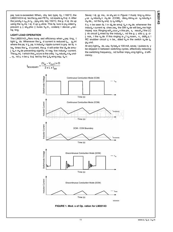
LM20143
If different start up times are needed the equation shown be-
low can be used to calculate the start up time.
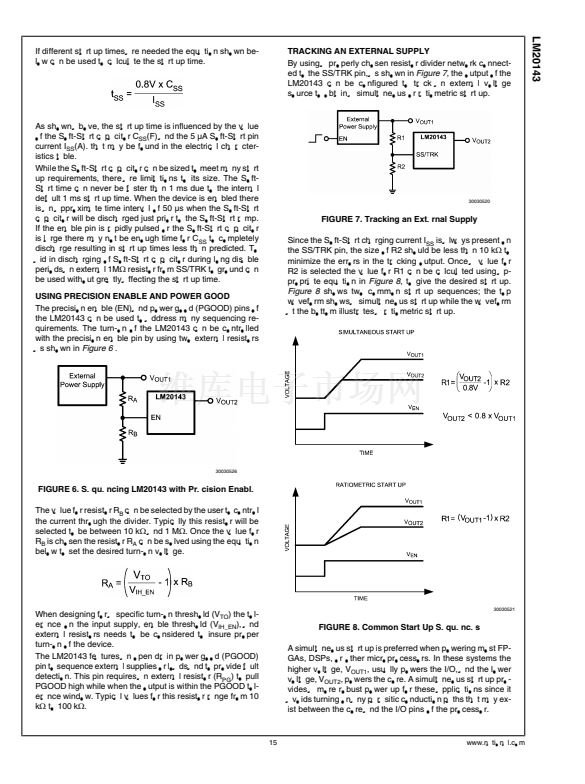
TRACKING AN EXTERNAL SUPPLY
By using a properly chosen resistor divider network connect-
ed to the SS/TRK pin, as shown in
Figure 7,
the output of the
LM20143 can be configured to track an external voltage
source to obtain a simultaneous or ratiometric start up.
As shown above, the start up time is influenced by the value
of the Soft-Start capacitor C
SS
(F) and the 5 碌A(chǔ) Soft-Start pin
current I
SS
(A). that may be found in the electrical character-
istics table.
While the Soft-Start capacitor can be sized to meet many start
up requirements, there are limitations to its size. The Soft-
Start time can never be faster than 1 ms due to the internal
default 1 ms start up time. When the device is enabled there
is an approximate time interval of 50 碌s when the Soft-Start
capacitor will be discharged just prior to the Soft-Start ramp.
If the enable pin is rapidly pulsed or the Soft-Start capacitor
is large there may not be enough time for C
SS
to completely
discharge resulting in start up times less than predicted. To
aid in discharging of Soft-Start capacitor during long disable
periods an external 1M鈩?resistor from SS/TRK to ground can
be used without greatly affecting the start up time.
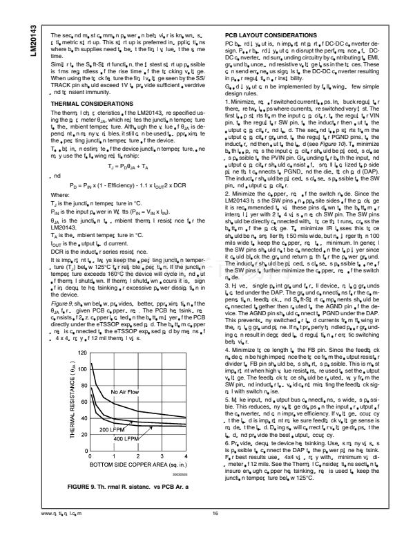
USING PRECISION ENABLE AND POWER GOOD
The precision enable (EN) and power good (PGOOD) pins of
the LM20143 can be used to address many sequencing re-
quirements. The turn-on of the LM20143 can be controlled
with the precision enable pin by using two external resistors
as shown in
Figure 6
.
30030520
FIGURE 7. Tracking an External Supply
Since the Soft-Start charging current I
SS
is always present on
the SS/TRK pin, the size of R2 should be less than 10 k鈩?to
minimize the errors in the tracking output. Once a value for
R2 is selected the value for R1 can be calculated using ap-
propriate equation in
Figure 8,
to give the desired start up.
Figure 8
shows two common start up sequences; the top
waveform shows a simultaneous start up while the waveform
at the bottom illustrates a ratiometric start up.
30030526
FIGURE 6. Sequencing LM20143 with Precision Enable
The value for resistor R
B
can be selected by the user to control
the current through the divider. Typically this resistor will be
selected to be between 10 k鈩?and 1 M鈩? Once the value for
R
B
is chosen the resistor R
A
can be solved using the equation
below to set the desired turn-on voltage.
When designing for a specific turn-on threshold (V
TO
) the tol-
erance on the input supply, enable threshold (V
IH_EN
), and
external resistors needs to be considered to insure proper
turn-on of the device.
The LM20143 features an open drain power good (PGOOD)
pin to sequence external supplies or loads and to provide fault
detection. This pin requires an external resistor (R
PG
) to pull
PGOOD high while when the output is within the PGOOD tol-
erance window. Typical values for this resistor range from 10
k鈩?to 100 k鈩?
30030521
FIGURE 8. Common Start Up Sequences
A simultaneous start up is preferred when powering most FP-
GAs, DSPs, or other microprocessors. In these systems the
higher voltage, V
OUT1
, usually powers the I/O, and the lower
voltage, V
OUT2
, powers the core. A simultaneous start up pro-
vides a more robust power up for these applications since it
avoids turning on any parasitic conduction paths that may ex-
ist between the core and the I/O pins of the processor.
15
www.national.com


 1
1
 2
2
 3
3
 4
4
 5
5
 6
6
 7
7
 8
8
 9
9
 10
10
 11
11
 12
12
 13
13
 14
14
 15
15
 16
16
 17
17
 18
18
 19
19
 20
20
