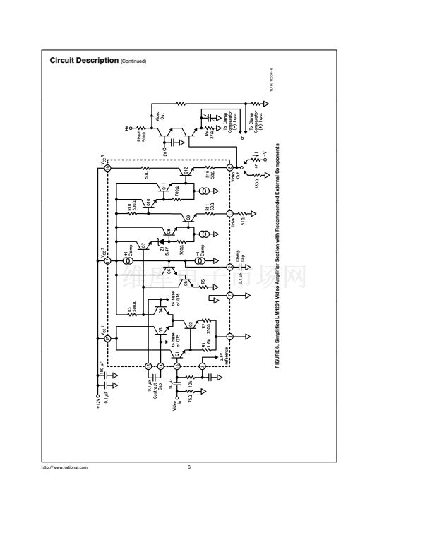
Applications Information
(Continued)
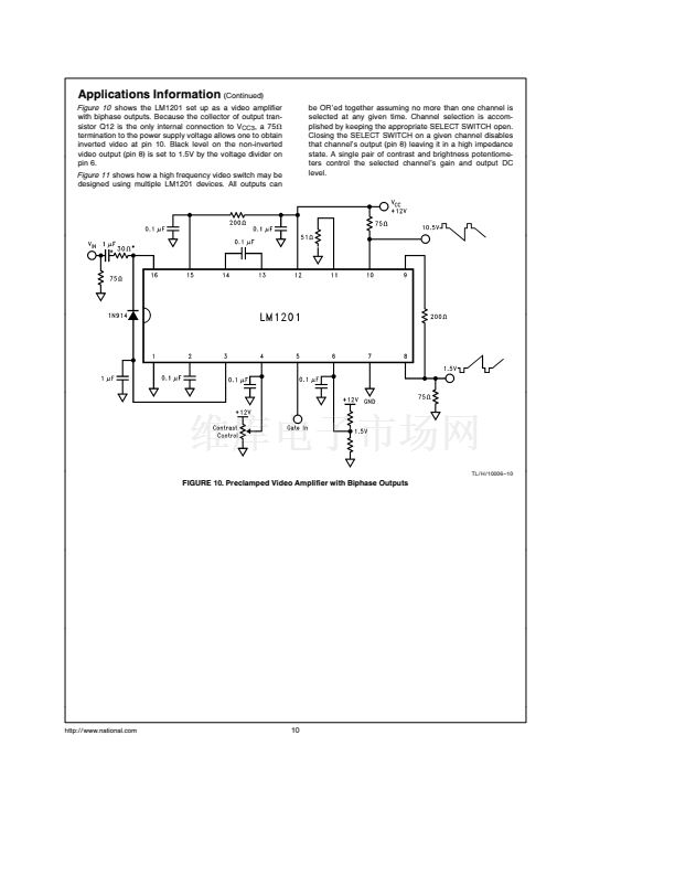
Figure 10
shows the LM1201 set up as a video amplifier
with biphase outputs Because the collector of output tran-
sistor Q12 is the only internal connection to V
CC3
a 75X
termination to the power supply voltage allows one to obtain
inverted video at pin 10 Black level on the non-inverted
video output (pin 8) is set to 1 5V by the voltage divider on
pin 6
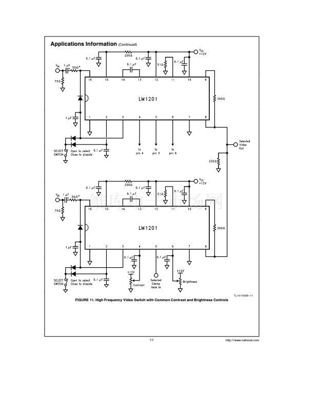
Figure 11
shows how a high frequency video switch may be
designed using multiple LM1201 devices All outputs can
be OR鈥檈d together assuming no more than one channel is
selected at any given time Channel selection is accom-
plished by keeping the appropriate SELECT SWITCH open
Closing the SELECT SWITCH on a given channel disables
that channel鈥檚 output (pin 8) leaving it in a high impedance
state A single pair of contrast and brightness potentiome-
ters control the selected channel鈥檚 gain and output DC
level
TL H 10006 鈥?10
FIGURE 10 Preclamped Video Amplifier with Biphase Outputs
http
www national com
10


 1
1
 2
2
 3
3
 4
4
 5
5
 6
6
 7
7
 8
8
 9
9
 10
10
 11
11
 12
12
 13
13
 14
14
 15
15
 16
16
