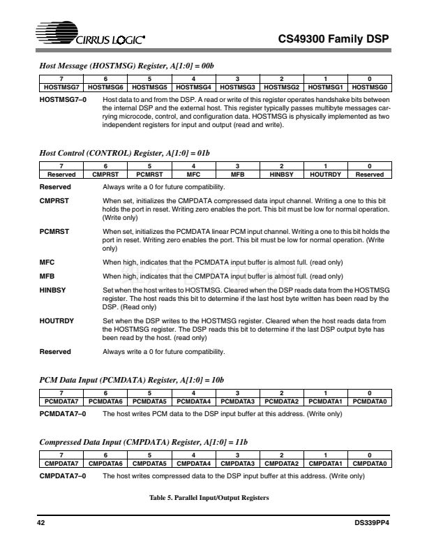
CS49300 Family DSP
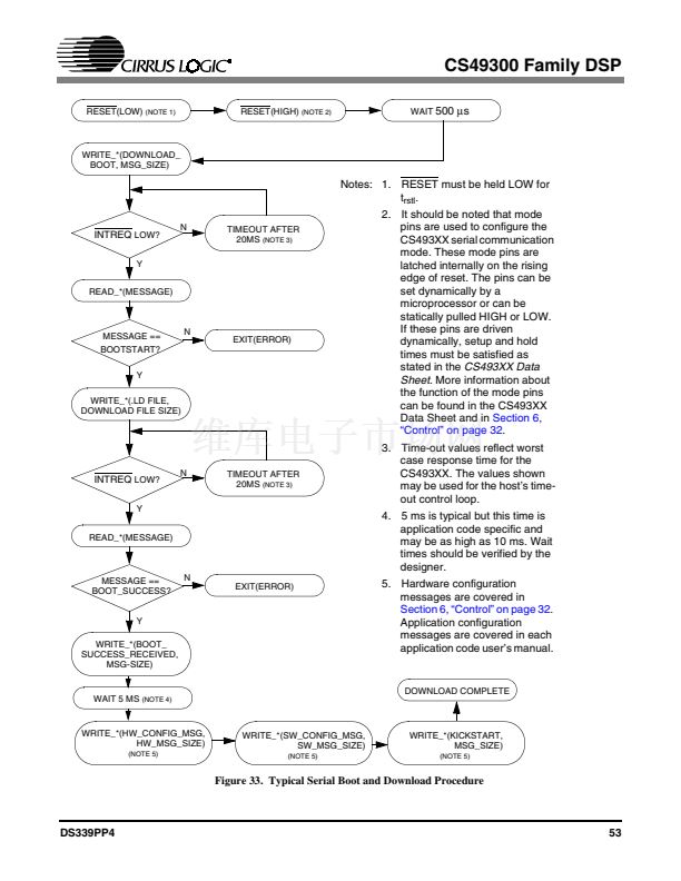
RESET(LOW)
(NOTE 1)
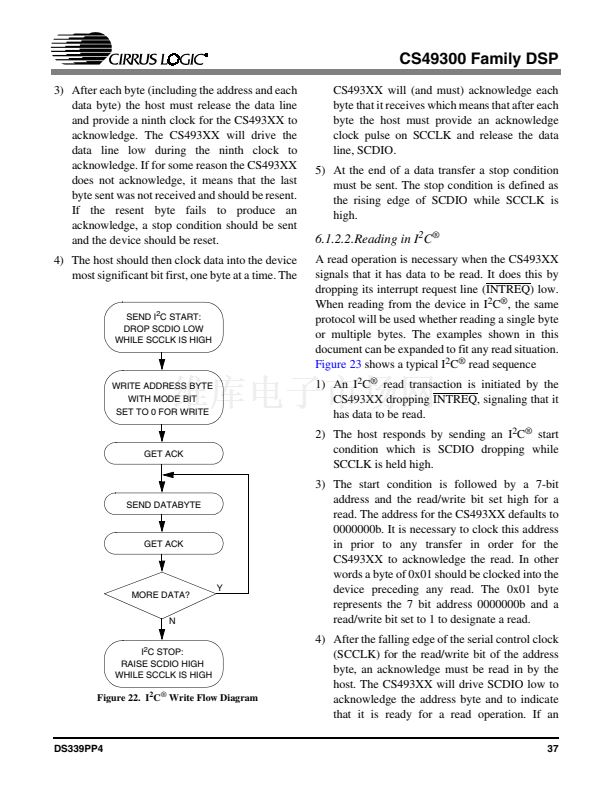
RESET(HIGH)
(NOTE 2)
WAIT
500
碌s
WRITE_*(DOWNLOAD_
BOOT, MSG_SIZE)
READ HOSTCTL
REGISTER
N
HOUTRDY LOW?
Y
READ_*(MESSAGE)
TIMEOUT AFTER
20MS
(NOTE 3)
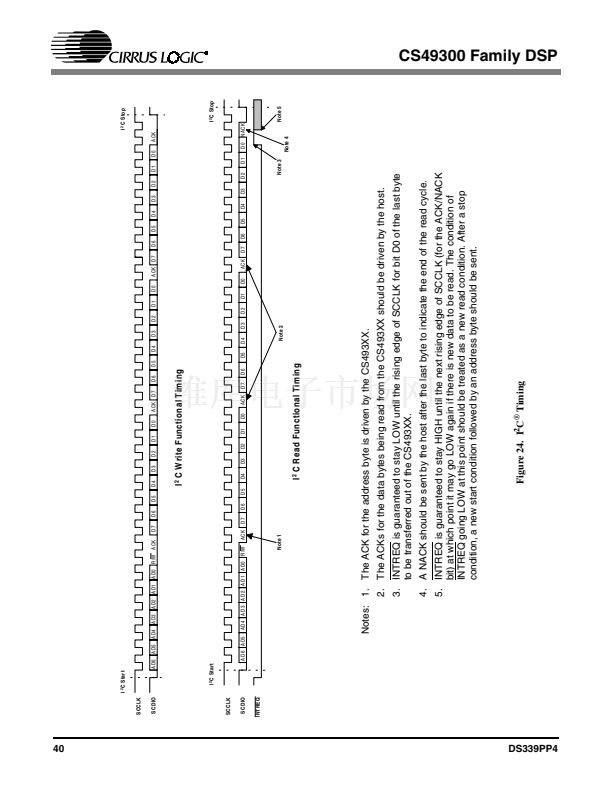
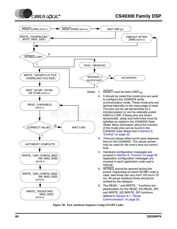
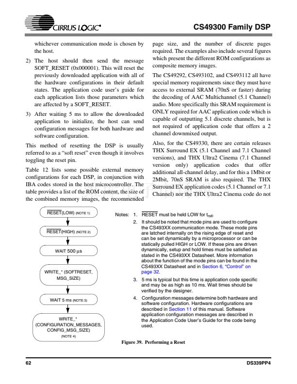
Notes: 1. RESET must be held LOW for
t
rstl
.
2. It should be noted that mode
pins are used to configure the
CS493XX serial communication
mode. These mode pins are
latched internally on the rising
edge of reset. The pins can be
set dynamically by a
microprocessor or can be
statically pulled HIGH or LOW. If
these pins are driven
dynamically, setup and hold
times must be satisfied as stated
in the
CS493XX Data Sheet.
More information about the
function of the mode pins can be
found in the CS493XX Data
Sheet and in
Section 6, 鈥淐ontrol鈥?/span>
on page 32.
3. Time-out values reflect worst
case response time for the
CS493XX. The values shown
may be used for the host鈥檚 time-
out control loop.
4. 5 ms is typical but this time is
application code specific and
may be as high as 10 ms. Wait
times should be verified by the
designer.
MESSAGE ==
BOOTSTART?
Y
WRITE_*(.LD FILE,
DOWNLOAD FILE SIZE)
N
EXIT(ERROR)
READ HOSTCTL
REGISTER
N
HOUTRDY LOW?
Y
READ_*(MESSAGE)
TIMEOUT AFTER
20MS
(NOTE 3)
MESSAGE ==
BOOT_SUCCESS?
Y
WRITE_*(BOOT_
SUCCESS_RECEIVED,
MSG-SIZE)
N
EXIT(ERROR)
5. Hardware configuration
messages are covered in
Section 6, 鈥淐ontrol鈥?on page 32.
Application configuration
messages are covered in each
application code user鈥檚 manual.
WAIT 5 MS
(NOTE 4)
DOWNLOAD COMPLETE
WRITE_*(HW_CONFIG_MSG,
HW_MSG_SIZE)
(NOTE 5)
WRITE_*(SW_CONFIG_MSG,
SW_MSG_SIZE)
(NOTE 5)
WRITE_*(KICKSTART,
MSG_SIZE)
(NOTE 5)
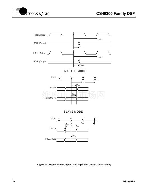
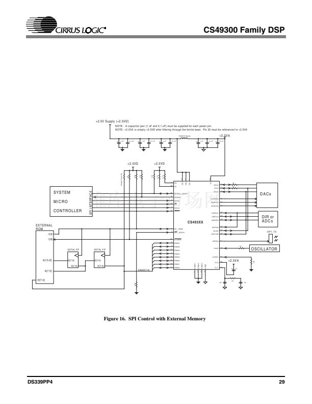
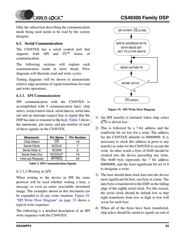
Figure 34. Typical Parallel Boot and Download Procedure
54
DS339PP4


 1
1
 2
2
 3
3
 4
4
 5
5
 6
6
 7
7
 8
8
 9
9
 10
10
 11
11
 12
12
 13
13
 14
14
 15
15
 16
16
 17
17
 18
18
 19
19
 20
20
 21
21
 22
22
 23
23
 24
24
 25
25
 26
26
 27
27
 28
28
 29
29
 30
30
 31
31
 32
32
 33
33
 34
34
 35
35
 36
36
 37
37
 38
38
 39
39
 40
40
 41
41
 42
42
 43
43
 44
44
 45
45
 46
46
 47
47
 48
48
 49
49
 50
50
 51
51
 52
52
 53
53
 54
54
 55
55
 56
56
 57
57
 58
58
 59
59
 60
60
 61
61
 62
62
 63
63
 64
64
 65
65
 66
66
 67
67
 68
68
 69
69
 70
70
 71
71
 72
72
 73
73
 74
74
 75
75
 76
76
 77
77
 78
78
 79
79
 80
80
 81
81
 82
82
 83
83
 84
84
 85
85
 86
86
