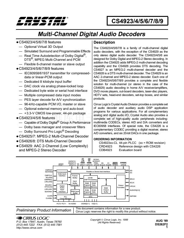
CS4923/4/5/6/7/8/9
In parallel host mode, the CS4923/4/5/6/7/8/9 can
accept PCM data written through the byte-wide
host interface to address 10b (A1 high, A0 low). In
this mode, there is a close connection between the
CS4923/4/5/6/7/8/9 application code and the host
processor that is delivering the PCM data. The
PCMRST bit of the CONTROL register provides
absolute software/hardware synchronization by
initializing the input channel to uniquely recognize
the first write to the byte-wide PCMDATA port.
Toggling PCMRST high and low informs the DSP
that the next sample read from the PCMDATA port
is the first sample of the left channel. In this
fashion, the CS492X can translate successive byte
writes into a variable number of channels with a
variable PCM sample size. In the most simple case,
the CS492X can receive stereo 8-bit PCM one byte
at a time with the internal DSP assigning the first
8-bit write (after PCMRST) to the left channel and
the second 8-bit write to the right channel. For
16-bit PCM, it assigns the first two 8-bit writes
(after PCMRST) to the left channel and the next
two writes to the right channel.
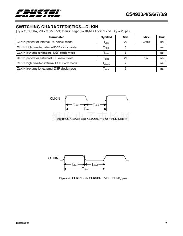
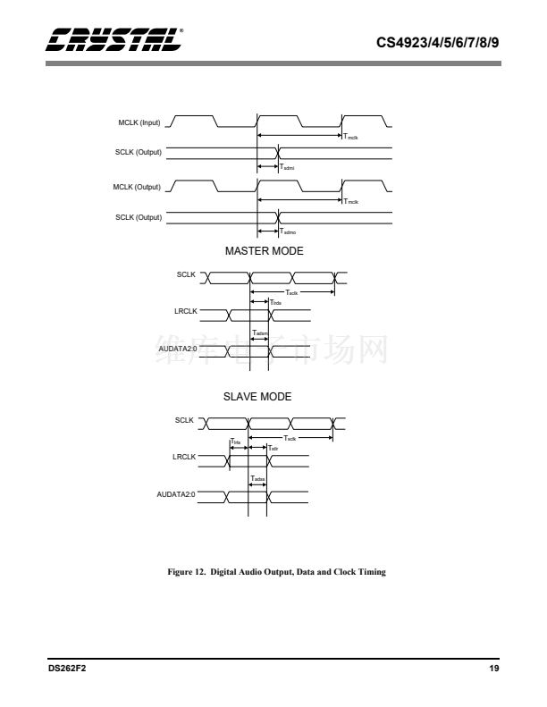
MCLK is the master clock and is firmware
configurable to be either an input or an output. If
MCLK is to be used as an output, the internal PLL
must be used. As an output MCLK can be
configured to provide a 128Fs, 256Fs or 512Fs
clock, where Fs is the output sample rate.
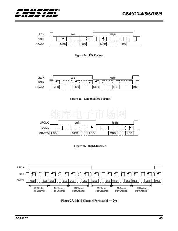
SCLK is the bit clock used to clock data out on
AUDATA0, AUDATA1 and AUDATA2. LRCLK
is the data framing clock whose frequency is
typically equal to the sampling frequency. Both
LRCLK and SCLK can be configured as either
inputs (Slave mode) or outputs (Master mode).
When LRCLK and SCLK are configured as inputs,
MCLK is a don鈥檛 care as an input. When LRCLK
and SCLK are configured as outputs, they are
derived from MCLK. Whether MCLK is
configured as an input or an output, an internal
divider from the MCLK signal is used to produce
LRCLK and SCLK. The ratios shown in table 13
give the possible SCLK values for different MCLK
frequencies (all values in terms of the sampling
frequency, Fs).
MCLK
(Fs)
128
384**
256
512
SCLK (Fs)
64
128
X
X
X
X
X
X
7.5 Digital Audio Output Port
The Digital Audio Output port, or DAO, is the port
used for digital output from the DSP. Table 12
shows the signals associated with the DAO. As
there are many modes that are firmware
configurable on the DAO, please consult the
Hardware User鈥檚 Guide and the application code
user鈥檚 guides to determine which modes are
supported by the download code being used.
Pin Name
AUDAT2
AUDAT1
AUDAT0
LRCLK
SCLK
MCLK
XMT958
Pin Description
Serial Data In
Serial Data In
Serial Data In
Frame Clock
Serial Bit Clock
Master Clock
IEC60958 Transmitter
Pin Number
39
40
41
42
43
44
3
32
X
X
X
X
48
X
256
512
X
X
X
** For MCLK as an input only
Table 13. MCLK/SCLK Master Mode Ratios
Table 12. Digital Audio Output Port
AUDAT0 is configurable to provide six, four, or
two channels. AUDAT1 and AUDAT2 can both
output two channels of data. Typically all three
AUDAT outputs are used in left justified, I2S or
right justified modes. In this way all six channels of
surround (Left, Center, Right, Left Surround, Right
Surround and Subwoofer) are provided.
Alternatively the multi-channel mode can be
configured to provide single data line multi-
channel support. Please consult the Hardware
User鈥檚 Guide and the application code user鈥檚
DS262F2
47


 1
1
 2
2
 3
3
 4
4
 5
5
 6
6
 7
7
 8
8
 9
9
 10
10
 11
11
 12
12
 13
13
 14
14
 15
15
 16
16
 17
17
 18
18
 19
19
 20
20
 21
21
 22
22
 23
23
 24
24
 25
25
 26
26
 27
27
 28
28
 29
29
 30
30
 31
31
 32
32
 33
33
 34
34
 35
35
 36
36
 37
37
 38
38
 39
39
 40
40
 41
41
 42
42
 43
43
 44
44
 45
45
 46
46
 47
47
 48
48
 49
49
 50
50
 51
51
 52
52
 53
53
 54
54
 55
55
 56
56
