Three General Purpose outputs are provided to allow the equipment designer flexibility in configuring the
CS8416.
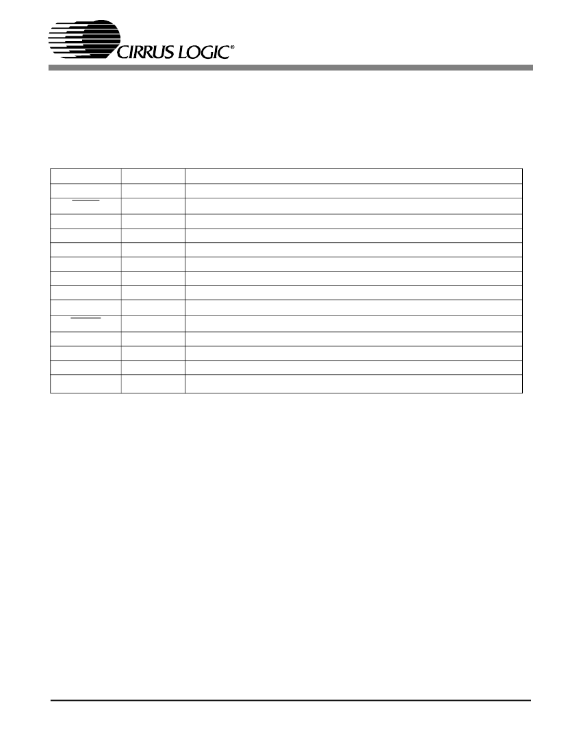
Fourteen signals are available to be routed to the GPOs.
State of EMPH bit in incoming stream. Same polarity as EMPHb bit.
鈮?/div>
88.1
Non-audio indicator for decoded input stream
Virtual LRCK
Fixed low Level
VDD fixed high level
F
S
X 512 (Note
13)
Table 3. GPO Pin Configurations
Notes: 13. Frequency = 25 MHz Max, duty cycle not guaranteed, target duty cycle = 50% @ F
S
= 48 kHz.
Codes 1110 to 1111 - Reserved
6.4
Interrupts
The CS8416 has a comprehensive interrupt capa-
bility. The INT pin may be set to be active low, ac-
tive high or active low with no active pull-up
transistor. This last mode is used for active low,
wired-OR hook- ups, with multiple peripherals
connected to the microcontroller interrupt input
pin.
Many conditions can cause an interrupt, as listed in
the interrupt status register descriptions. Each
source may be masked off through mask register
bits. In addition, each source may be set to rising
edge, falling edge, or level sensitive. Combined
with the option of level sensitive or edge sensitive
modes within the microcontroller, many different
configurations are possible, depending on the
needs of the equipment designer.
22
DS578PP2


 1
1
 2
2
 3
3
 4
4
 5
5
 6
6
 7
7
 8
8
 9
9
 10
10
 11
11
 12
12
 13
13
 14
14
 15
15
 16
16
 17
17
 18
18
 19
19
 20
20
 21
21
 22
22
 23
23
 24
24
 25
25
 26
26
 27
27
 28
28
 29
29
 30
30
 31
31
 32
32
 33
33
 34
34
 35
35
 36
36
 37
37
 38
38
 39
39
 40
40
 41
41
 42
42
 43
43
 44
44
 45
45
 46
46
 47
47
 48
48
