CS8415A
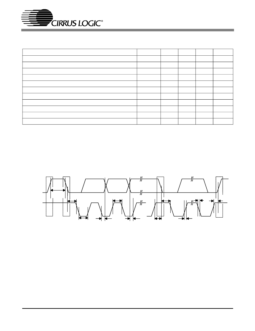
SWITCHING CHARACTERISTICS - CONTROL PORT - I
2
C MODE
(Note 15, Inputs: Logic 0 = 0 V, Logic 1 = VL+; C
L
= 20 pF)
Parameter
SCL Clock Frequency
Bus Free Time Between Transmissions
Start Condition Hold Time (prior to first clock pulse)
Clock Low Time
Clock High Time
Setup Time for Repeated Start Condition
SDA Hold Time from SCL Falling
SDA Setup Time to SCL Rising
Rise Time of Both SDA and SCL Lines
Fall Time of Both SDA and SCL Lines
Setup Time for Stop Condition
Notes: 15. I
2
C protocol is supported only in 5V mode.
16. Data must be held for sufficient time to bridge the 25 ns transition time of SCL.
(Note 16)
Symbol
f
scl
t
buf
t
hdst
t
low
t
high
t
sust
t
hdd
t
sud
t
r
t
f
t
susp
Min
-
4.7
4.0
4.7
4.0
4.7
0
250
-
-
4.7
Typ
-
-
-
-
-
-
-
-
-
-
-
Max
100
-
-
-
-
-
-
-
25
25
-
Units
kHz
碌s
碌s
碌s
碌s
碌s
碌s
ns
ns
ns
碌s
Stop
SDA
t buf
SCL
Start
Repeated
Start
Stop
t hdst
t high
t
hdst
tf
t susp
t
low
t
hdd
t sud
t sust
tr
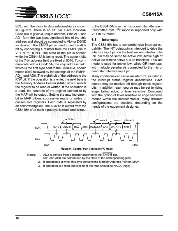
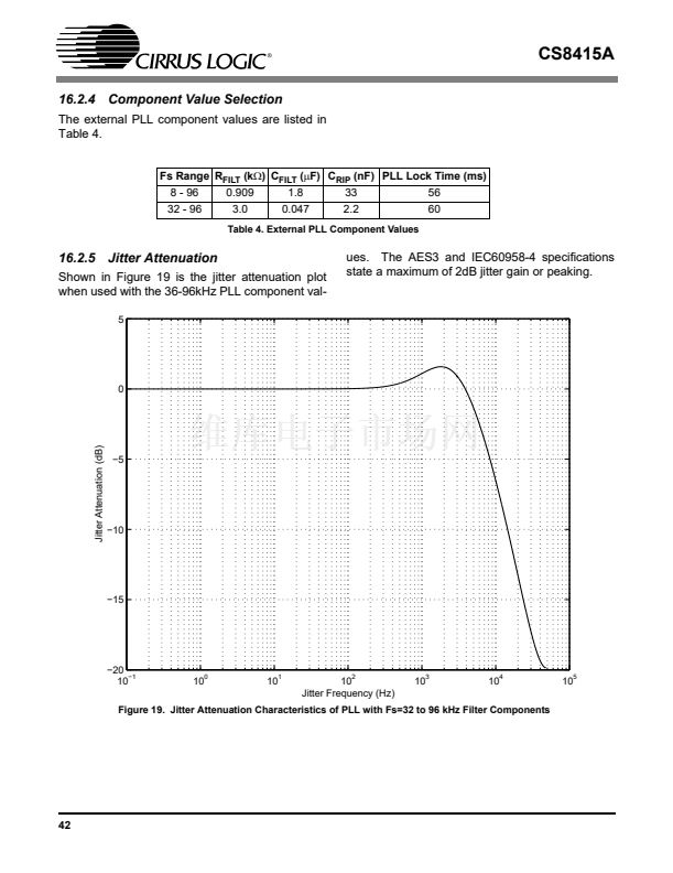
Figure 4. I
2
C Mode timing
9


 1
1
 2
2
 3
3
 4
4
 5
5
 6
6
 7
7
 8
8
 9
9
 10
10
 11
11
 12
12
 13
13
 14
14
 15
15
 16
16
 17
17
 18
18
 19
19
 20
20
 21
21
 22
22
 23
23
 24
24
 25
25
 26
26
 27
27
 28
28
 29
29
 30
30
 31
31
 32
32
 33
33
 34
34
 35
35
 36
36
 37
37
 38
38
 39
39
 40
40
 41
41
 42
42
