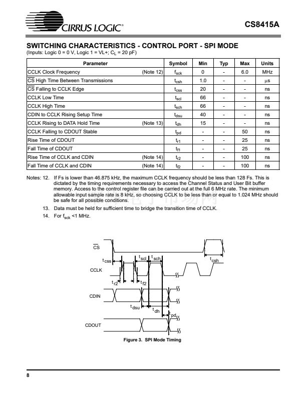
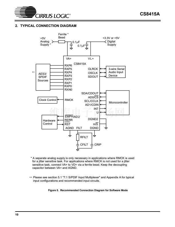
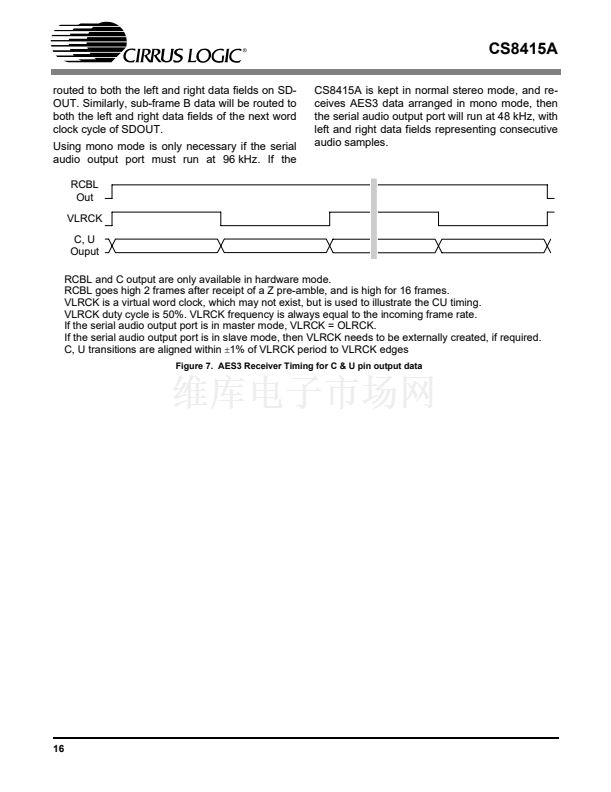
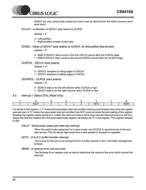
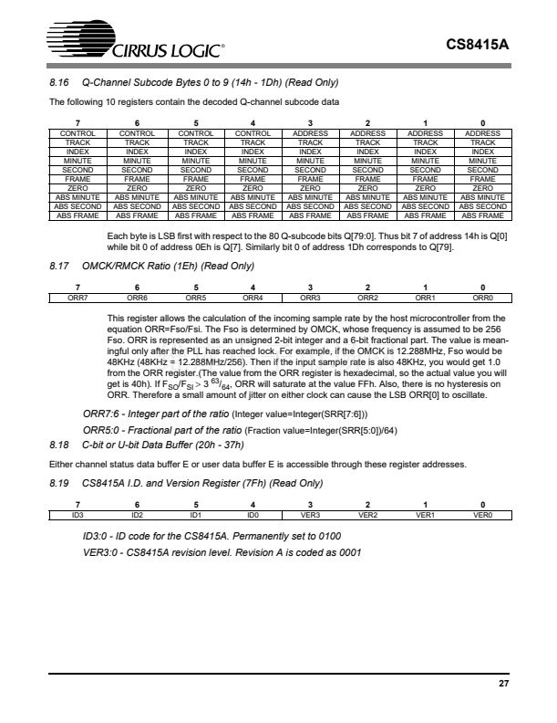
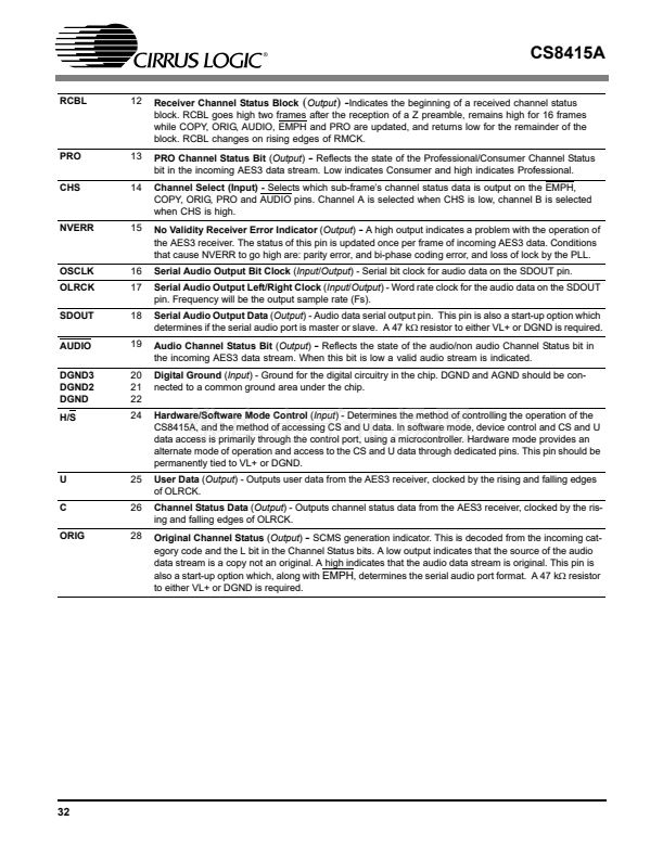
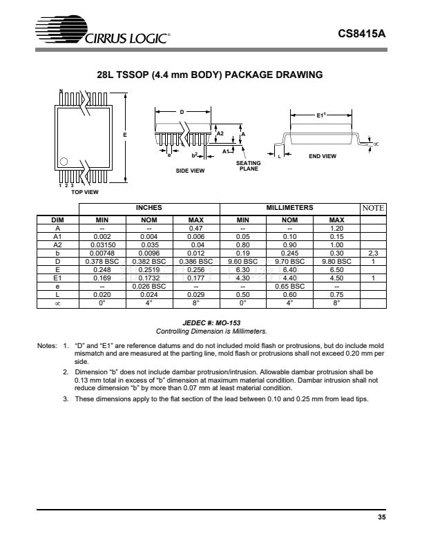
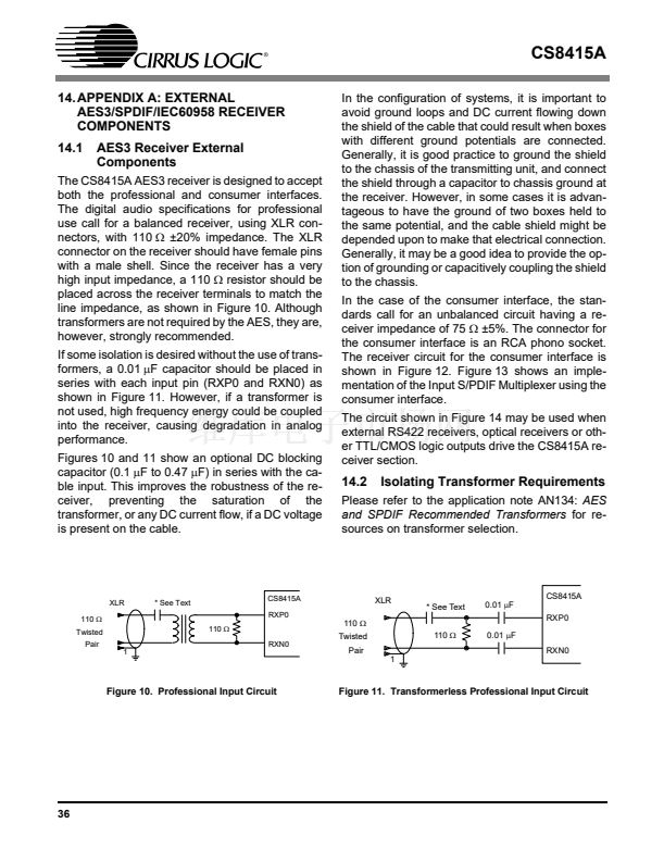
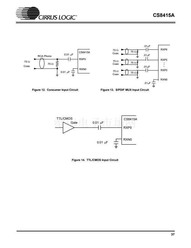
CS8415A
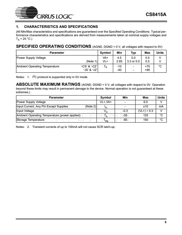
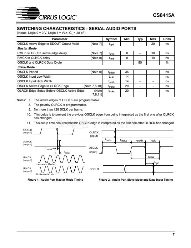
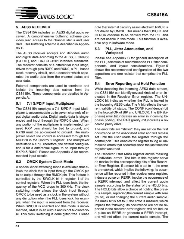
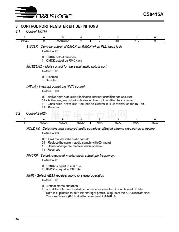
SWITCHING CHARACTERISTICS - SERIAL AUDIO PORTS
(Inputs: Logic 0 = 0 V, Logic 1 = VL+; C
L
= 20 pF)
Parameter
OSCLK Active Edge to SDOUT Output Valid
Master Mode
RMCK to OSCLK active edge delay
RMCK to OLRCK delay
OSCLK and OLRCK Duty Cycle
Slave Mode
OSCLK Period
OSCLK Input Low Width
OSCLK Input High Width
OSCLK Active Edge to OLRCK Edge
(Note 7,8,10)
(Note
7,8,11)
OLRCK Edge Setup Before OSCLK Active Edge
(Note 9)
t
sckw
t
sckl
t
sckh
t
lrckd
t
lrcks
36
14
14
20
20
-
-
-
-
-
-
-
-
-
-
ns
ns
ns
ns
ns
(Note 7)
(Note 8)
t
smd
t
lmd
0
0
-
-
-
50
10
10
-
ns
ns
%
(Note 7)
Symbol
t
dpd
Min
-
Typ
-
Max
20
Units
ns
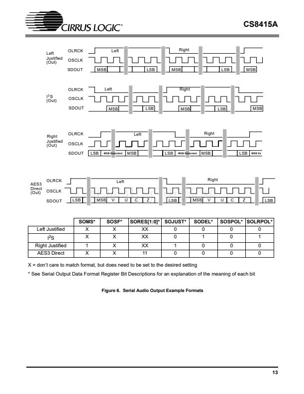
Notes: 7. The active edges of OSCLK are programmable.
8. The polarity OLRCK is programmable.
9. No more than 128 SCLK per frame.
10. This delay is to prevent the previous OSCLK edge from being interpreted as the first one after OLRCK
has changed.
11. This setup time ensures that this OSCLK edge is interpreted as the first one after OLRCK has changed.
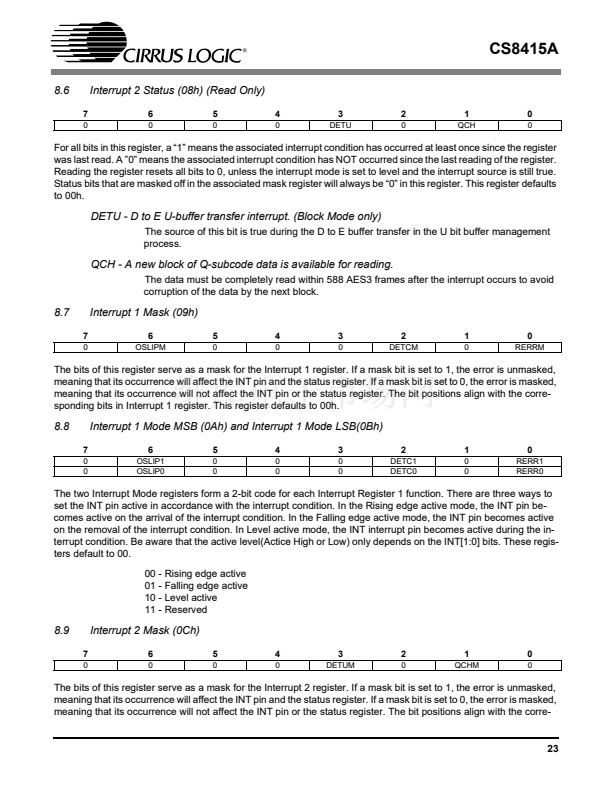
O SC LK
(o u tp u t)
OLRCK
(input)
O LR C K
(o u tp u t)
t sm d
t
RMCK
(o u tp u t)
H a rd w a re M o d e
RMCK
(o u tp u t)
S o ftw a re M o d e
lm d
t lrckd
OSCLK
(input)
t lrcks
t sckh
t sckl
t sckw
t dpd
SDOUT
Figure 1. Audio Port Master Mode Timing
Figure 2. Audio Port Slave Mode and Data Input Timing
7


 1
1
 2
2
 3
3
 4
4
 5
5
 6
6
 7
7
 8
8
 9
9
 10
10
 11
11
 12
12
 13
13
 14
14
 15
15
 16
16
 17
17
 18
18
 19
19
 20
20
 21
21
 22
22
 23
23
 24
24
 25
25
 26
26
 27
27
 28
28
 29
29
 30
30
 31
31
 32
32
 33
33
 34
34
 35
35
 36
36
 37
37
 38
38
 39
39
 40
40
 41
41
 42
42
