CS8415A
12. APPLICATIONS
12.1
Reset, Power Down and Start-up
When RST is low, the CS8415A enters a low pow-
er mode and all internal states are reset, including
the control port and registers, and the outputs are
muted. When RST is high, the control port be-
comes operational and the desired settings should
be loaded into the control registers. Writing a 1 to
the RUN bit will then cause the part to leave the low
power state and begin operation. After the PLL has
settled, the serial audio outputs will be enabled.
Some options within the CS8415A are controlled
by a start-up mechanism. During the reset state,
some of the output pins are reconfigured internally
to be inputs. Immediately upon exiting the reset
state, the level of these pins is sensed. The pins
are then switched to be outputs. This mechanism
allows output pins to be used to set alternative
modes in the CS8415A by connecting a 47 K鈩?re-
sistor to between the pin and either VL+ (HI) or
DGND (LO). For each mode, every start-up option
select pin MUST have an external pull-up or pull-
down resistor. In software mode, the only start-up
option pin is EMPH, which is used to set a chip ad-
dress bit for the control port in I
2
C mode. The hard-
ware mode uses many start-up options, which are
detailed in the hardware definition section at the
end of this data sheet.
ily members are resident in the same system, al-
lowing common software modules.
The CS8415A 4-bit revision code is also available.
This allows the software driver for the CS8415A to
identify which revision of the device is in a particu-
lar system, and modify its behavior accordingly. To
allow for future revisions, it is strongly recommend
that the revision code is read into a variable area
within the microcontroller, and used wherever ap-
propriate as revision details become known.
12.3
Power Supply, Grounding, and PCB
layout
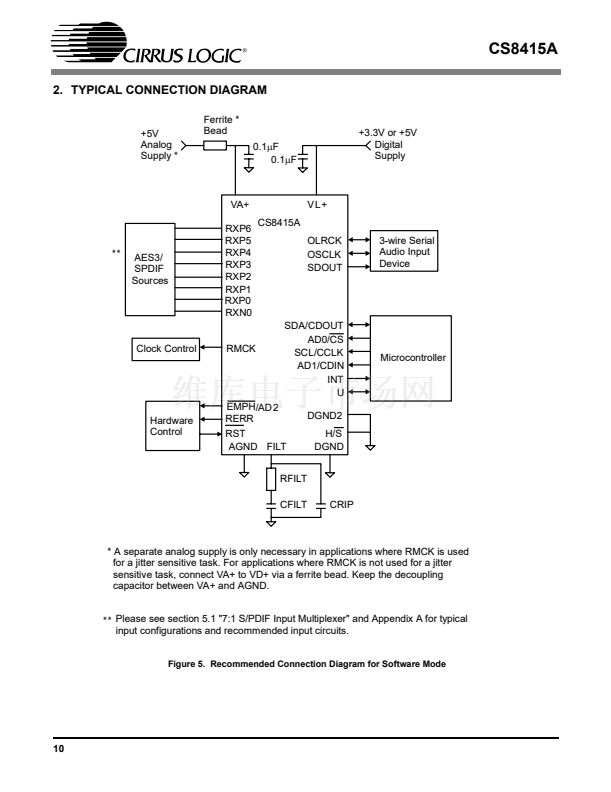
For most applications, the CS8415A can be oper-
ated from a single +5 V supply, following normal
supply decoupling practices, see Figure 5. Note
that the I
2
C protocol is supported only in 5V mode.
For applications where the recovered input clock,
output on the RMCK pin, is required to be low jitter,
then use a separate, quiet, analog +5 V supply for
VA+, decoupled to AGND. In addition, a separate
region of analog ground plane around the FILT,
AGND, VA+, RXP0-6 and RXN0 pins is recom-
mended.
Extensive use of power and ground planes, ground
plane fill in unused areas and surface mount de-
coupling capacitors are recommended. Decou-
pling capacitors should be mounted on the same
side of the board as the CS8415A to minimize in-
ductance effects, and all decoupling capacitors
should be as close to the CS8415A as possible.
12.2
ID Code and Revision Code
The CS8415A has a register that contains a 4-bit
code to indicate that the addressed device is a
CS8415A. This is useful when other CS84XX fam-
33


 1
1
 2
2
 3
3
 4
4
 5
5
 6
6
 7
7
 8
8
 9
9
 10
10
 11
11
 12
12
 13
13
 14
14
 15
15
 16
16
 17
17
 18
18
 19
19
 20
20
 21
21
 22
22
 23
23
 24
24
 25
25
 26
26
 27
27
 28
28
 29
29
 30
30
 31
31
 32
32
 33
33
 34
34
 35
35
 36
36
 37
37
 38
38
 39
39
 40
40
 41
41
 42
42
