ADVANCE
INFORMATION
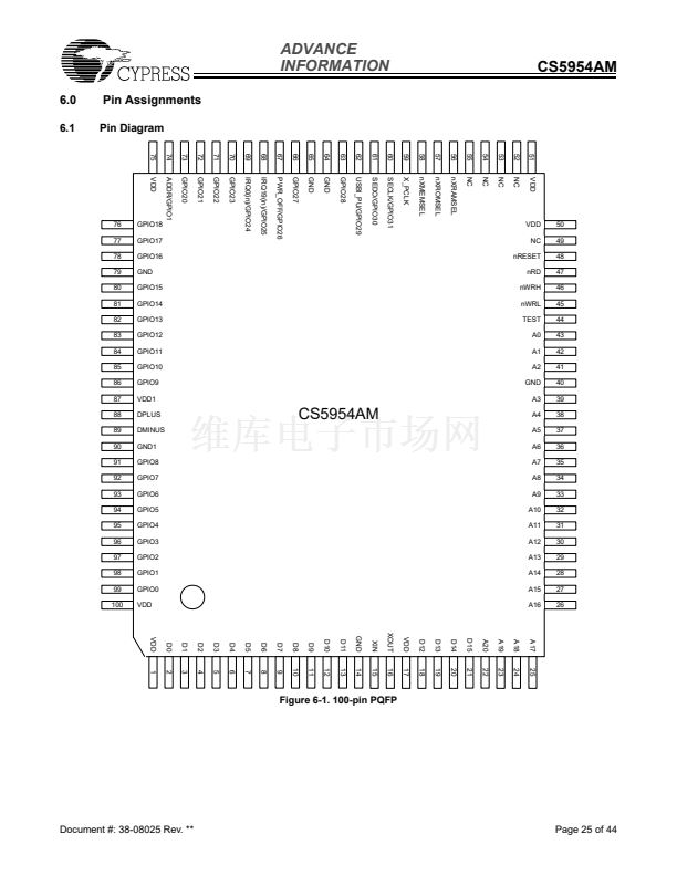
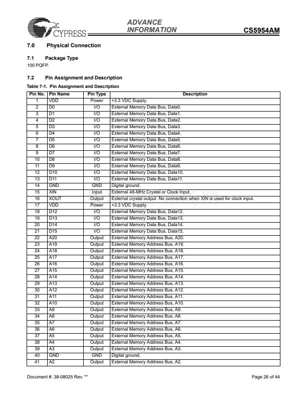
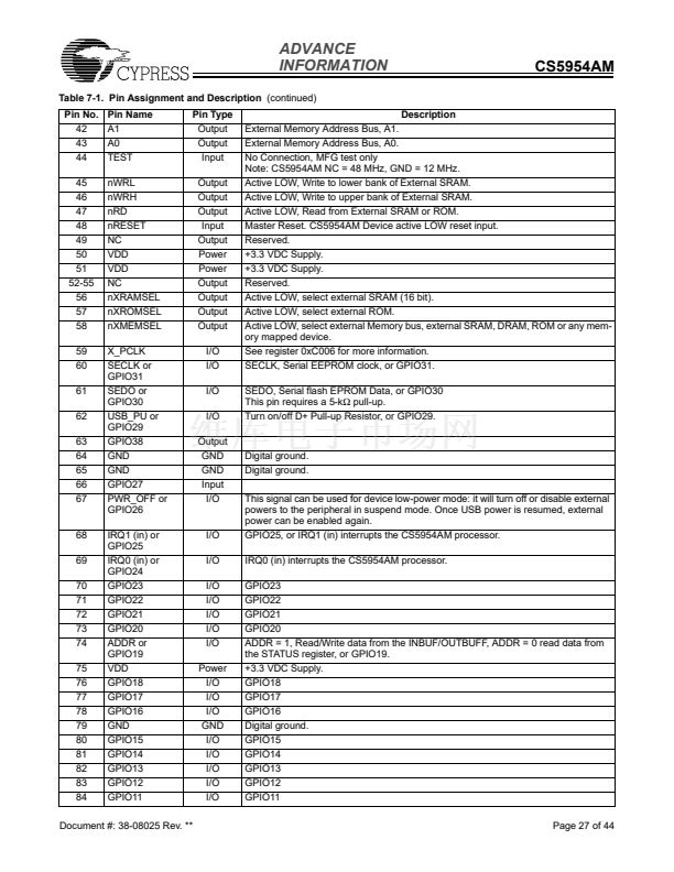
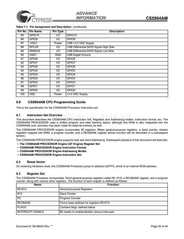
CS5954AM
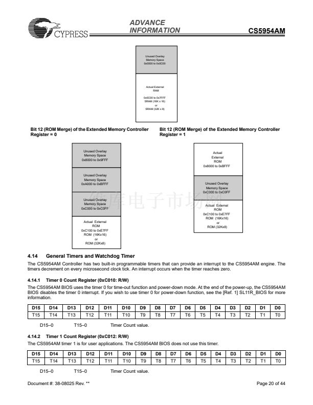
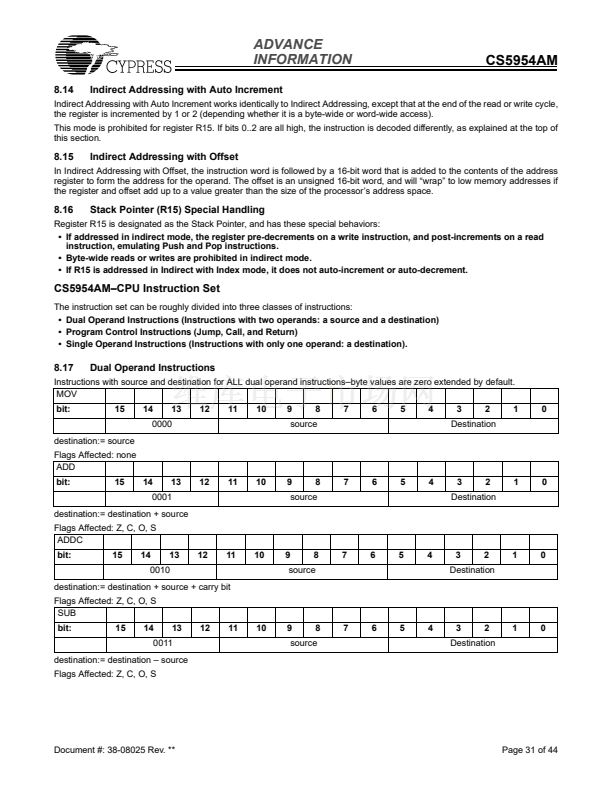
Unused Overlay
Memory Space
0x0000 to 0x0C00
Actual External
RAM
0x0C00 to 0x7FFF
SRAM (16K x 16)
or
SRAM (32K x 8)
Bit 12 (ROM Merge) of the Extended Memory Controller
Register = 0
Bit 12 (ROM Merge) of the Extended Memory Controller
Register = 1
Unused Overlay
Memory Space
0x8000 to 0x9FFF
Actual
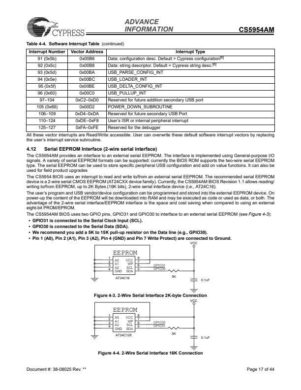
External
ROM
0x8000 to 0xBFFF
Unused Overlay
Memory Space
0xA000 to 0xBFFF
Unused Overlay
Memory Space
0xC000 to 0xC0FF
Unused Overlay
Memory Space
0xC000 to 0xC0FF
Actual External
ROM
0xC100 to 0xE7FF
ROM (16Kx16)
or
ROM (32Kx8)
Actual External
ROM
0xC100 to 0xE7FF
ROM (16Kx16)
or
ROM (32Kx8)
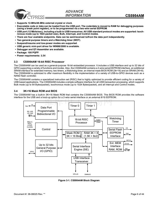
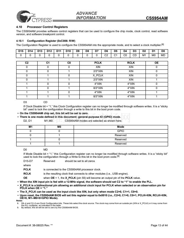
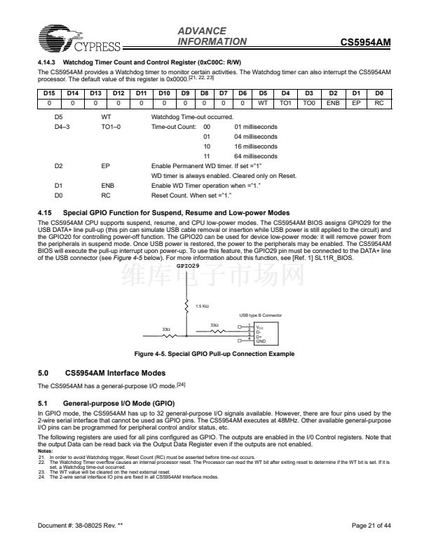
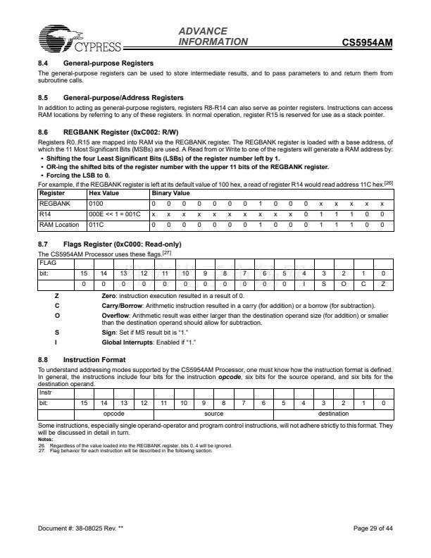
4.14
General Timers and Watchdog Timer
The CS5954AM Controller has two built-in programmable timers that can provide an interrupt to the CS5954AM engine. The
timers decrement on every microsecond clock tick. An interrupt occurs when the timer reaches zero.
4.14.1
Timer 0 Count Register (0xC010: R/W)
The CS5954AM BIOS uses the timer 0 for time-out function and power-down mode. At the end of the power-up, the CS5954AM
BIOS disables the timer 0 interrupt. If you wish to use timer 0 for power-down function, see the [Ref. 1] SL11R_BIOS for more
information.
D15
T15
D14
T14
D13
T13
D12
T12
D11
T11
D10
T10
D9
T9
D8
T8
D7
T7
D6
T6
D5
T5
D4
T4
D3
T3
D2
T2
D1
T1
D0
T0
D15鈥?
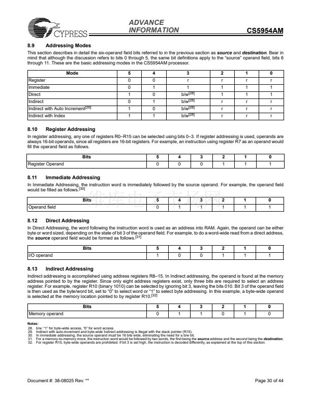
4.14.2
T15鈥?
Timer Count value.
Timer 1 Count Register (0xC012: R/W)
The CS5954AM timer 1 is for user applications. The CS5954AM BIOS does not use this timer.
D15
T15
D14
T14
D13
T13
D12
T12
D11
T11
D10
T10
D9
T9
D8
T8
D7
T7
D6
T6
D5
T5
D4
T4
D3
T3
D2
T2
D1
T1
D0
T0
D15鈥?
T15鈥?
Timer Count value.
Page 20 of 44
Document #: 38-08025 Rev. **


 1
1
 2
2
 3
3
 4
4
 5
5
 6
6
 7
7
 8
8
 9
9
 10
10
 11
11
 12
12
 13
13
 14
14
 15
15
 16
16
 17
17
 18
18
 19
19
 20
20
 21
21
 22
22
 23
23
 24
24
 25
25
 26
26
 27
27
 28
28
 29
29
 30
30
 31
31
 32
32
 33
33
 34
34
 35
35
 36
36
 37
37
 38
38
 39
39
 40
40
 41
41
 42
42
 43
43
 44
44
