CS49300 Family DSP
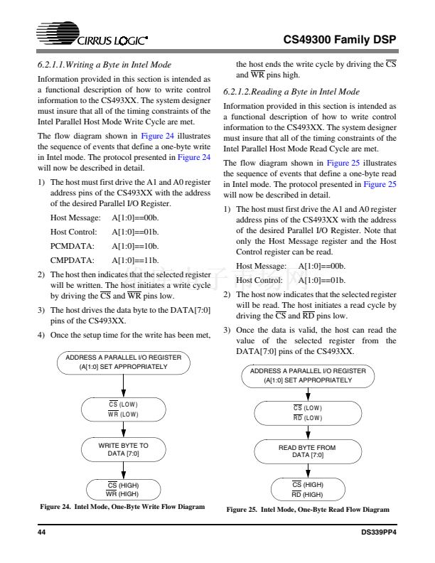
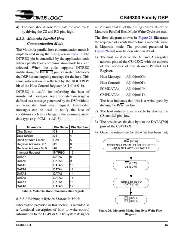
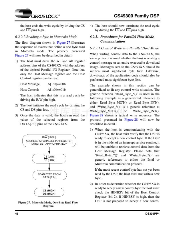
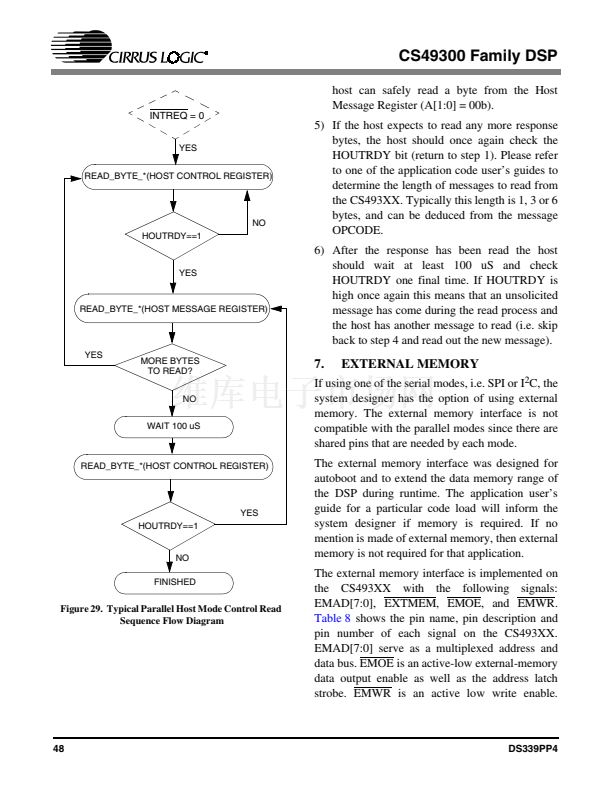
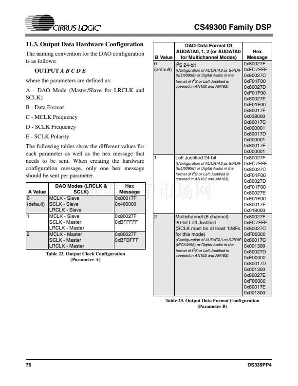
11.3. Output Data Hardware Configuration
The naming convention for the DAO configuration
is as follows:
OUTPUT
A B C D E
where the parameters are defined as:
A - DAO Mode (Master/Slave for LRCLK and
SCLK)
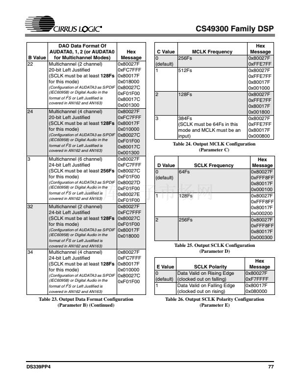
B - Data Format
C - MCLK Frequency
D - SCLK Frequency
E - SCLK Polarity
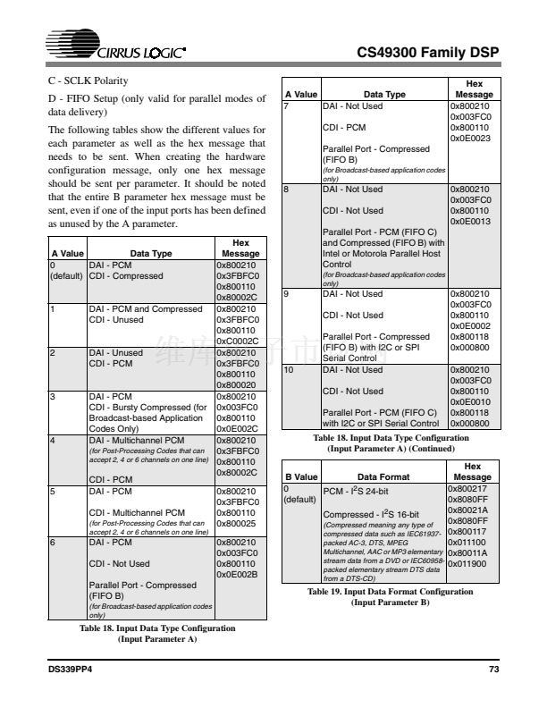
The following tables show the different values for
each parameter as well as the hex message that
needs to be sent. When creating the hardware
configuration message, only one hex message
should be sent per parameter.
DAO Modes (LRCLK &
A Value
SCLK)
0
MCLK - Slave
(default) SCLK - Slave
LRCLK - Slave
1
MCLK - Slave
SCLK - Master
LRCLK - Master
2
MCLK - Master
SCLK - Master
LRCLK - Master
Hex
Message
0x80017F
0x400000
0x80027F
0xBFFFFF
0x80027F
0xBFDFFF
DAO Data Format Of
AUDATA0, 1, 2 (or AUDATA0
Hex
B Value
for Multichannel Modes)
Message
0
0x80027F
I
2
S 24-bit
(default)
(Configuration of AUDATA3 as S/PDIF
0xFC7FFF
(IEC60958) or Digital Audio in the
0x80027C
2
S or Left Justified is
format of I
0xF01F00
covered in AN162 and AN163)
0x80027D
0xF01F00
0x80027E
0xF01F00
0x80017F
0x038000
0x80017C
0x000001
0x80017D
0x000001
0x80017E
0x000001
1
Left Justified 24-bit
0x80027F
(Configuration of AUDATA3 as S/PDIF
0xFC7FFF
(IEC60958) or Digital Audio in the
0x80027C
format of I
2
S or Left Justified is
0xF01F00
covered in AN162 and AN163)
0x80027D
0xF01F00
0x80027E
0xF01F00
0x80017F
0x018000
2
Multichannel (6 channel)
0x80027F
20-bit Left Justified
0xFC7FFF
(SCLK must be at least 128Fs 0x80027C
for this mode)
0xF00000
(Configuration of AUDATA3 as S/PDIF
0x80017C
(IEC60958) or Digital Audio in the
0x001300
format of I
2
S or Left Justified is
0x80027D
covered in AN162 and AN163)
0xF00000
0x80017D
0x001300
0x80027E
0xF00000
0x80017E
0x001300
Table 23. Output Data Format Configuration
(Parameter B)
Table 22. Output Clock Configuration
(Parameter A)
76
DS339PP4


 1
1
 2
2
 3
3
 4
4
 5
5
 6
6
 7
7
 8
8
 9
9
 10
10
 11
11
 12
12
 13
13
 14
14
 15
15
 16
16
 17
17
 18
18
 19
19
 20
20
 21
21
 22
22
 23
23
 24
24
 25
25
 26
26
 27
27
 28
28
 29
29
 30
30
 31
31
 32
32
 33
33
 34
34
 35
35
 36
36
 37
37
 38
38
 39
39
 40
40
 41
41
 42
42
 43
43
 44
44
 45
45
 46
46
 47
47
 48
48
 49
49
 50
50
 51
51
 52
52
 53
53
 54
54
 55
55
 56
56
 57
57
 58
58
 59
59
 60
60
 61
61
 62
62
 63
63
 64
64
 65
65
 66
66
 67
67
 68
68
 69
69
 70
70
 71
71
 72
72
 73
73
 74
74
 75
75
 76
76
 77
77
 78
78
 79
79
 80
80
 81
81
 82
82
 83
83
 84
84
 85
85
 86
86
