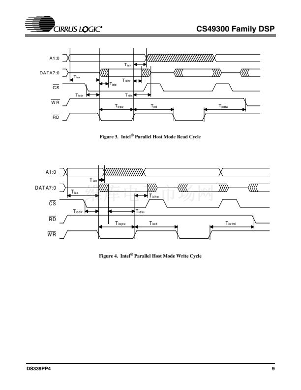
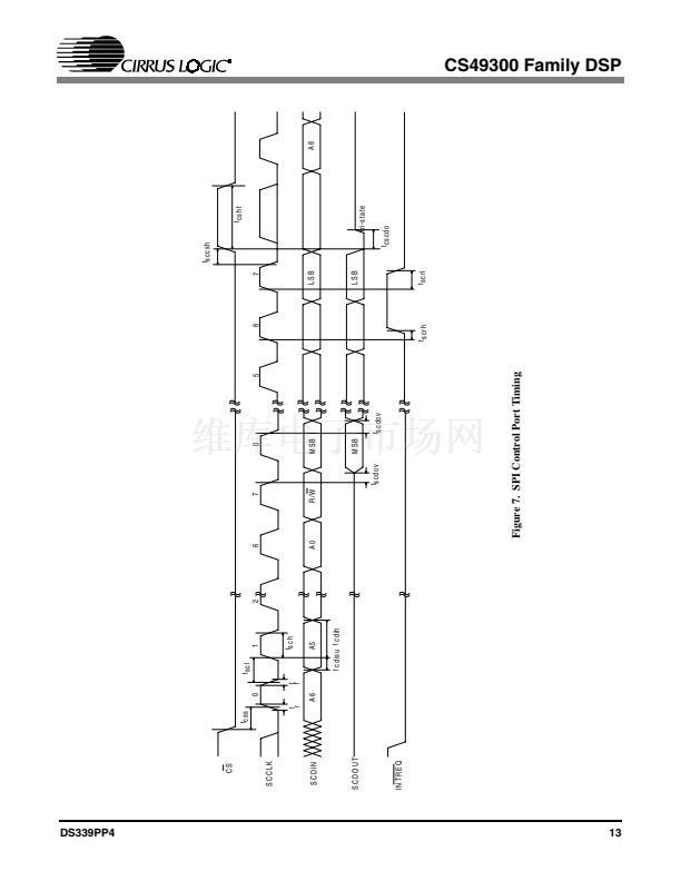
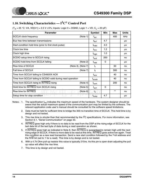
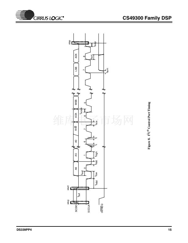
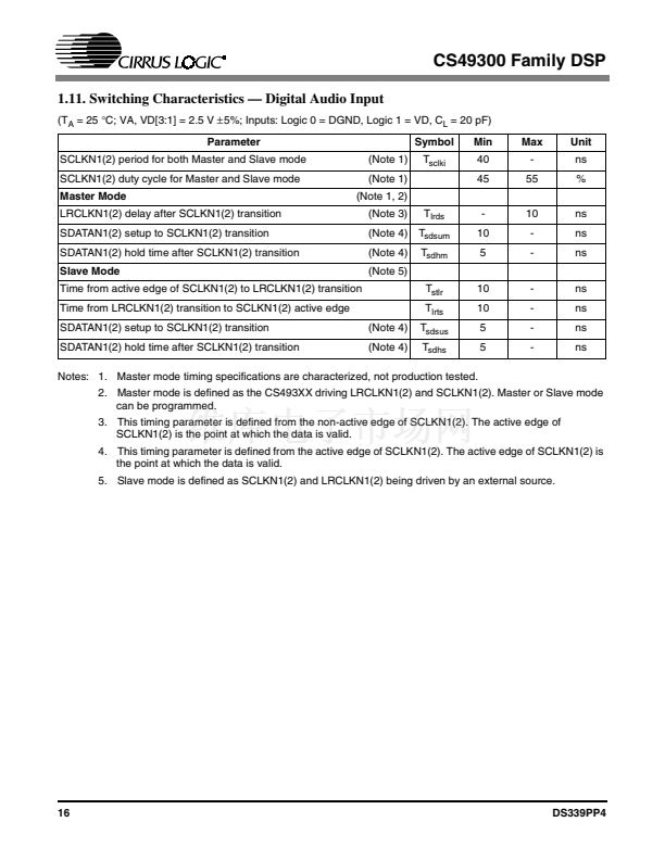
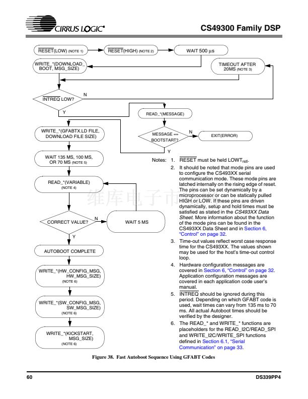
CS49300 Family DSP
1.10.
Switching Characteristics 鈥?I
2
C
廬
Control Port
(T
A
= 25
擄C;
VA, VD[3:1] = 2.5 V
鹵5%;
Inputs: Logic 0 = DGND, Logic 1 = VD, C
L
= 20 pF)
Parameter
SCCLK clock frequency
Bus free time between transmissions
Start-condition hold time (prior to first clock pulse)
Clock low time
Clock high time
SCDIO setup time to SCCLK rising
SCDIO hold time from SCCLK falling
Rise time of SCCLK
Fall time of SCCLK
Time from SCCLK falling to CS493XX ACK
Time from SCCLK falling to SCDIO valid during read operation
Time from SCCLK rising to INTREQ rising
Hold time for INTREQ from SCCLK rising
Rise time for INTREQ
Setup time for stop condition
(Note 4)
(Note 5)
(Note 6)
(Note 2)
(Note 3), (Note 7)
(Note 7)
(Note 1)
Symbol
f
scl
t
buf
t
hdst
t
low
t
high
t
sud
t
hdd
t
r
t
f
t
sca
t
scsdv
t
scrh
t
scrl
t
rr
t
susp
4.7
0
**
4.7
4.0
1.2
1.0
250
0
50
300
40
40
200
Min
Max
400
Units
kHz
碌s
碌s
碌s
碌s
ns
碌s
ns
ns
ns
ns
ns
ns
ns
碌s
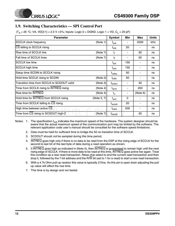
Notes:. 1. The specification f
scl
indicates the maximum speed of the hardware. The system designer should be
aware that the actual maximum speed of the communication port may be limited by the software. The
relevant application code user鈥檚 manual should be consulted for the software speed limitations.
2. Data must be held for sufficient time to bridge the 300-ns transition time of SCCLK. This hold time is by
design and not tested.
3. This rise time is
shorter
than that recommended by the I
2
C specifications. For more information, see
Section 6.1, 鈥淪erial Communication鈥?on page 33.
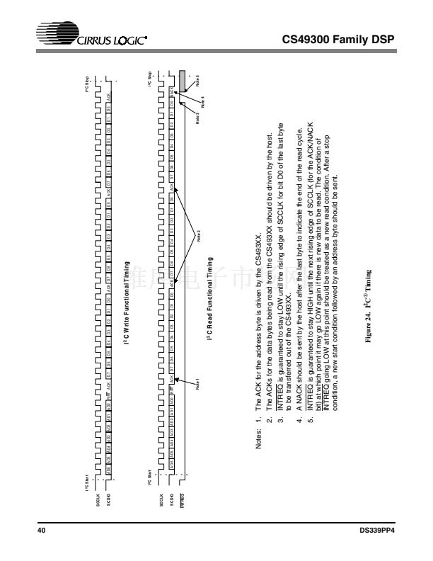
4. INTREQ goes high only if there is no data to be read from the DSP at the rising edge of SCCLK for the
last data bit of the last byte of data during a read operation as shown.
5. If INTREQ goes high as indicated in Note 8, then INTREQ is guaranteed to remain high until the next
rising edge of SCCLK. If there is more data to be read at this time, INTREQ goes active low again. Treat
this condition as a new read transaction. Send a new start condition followed by the 7-bit address and
the R/W bit (set to 1 for a read). This time is by design and is not tested.
6. With a 4.7k Ohm pull-up resistor this value is typically 215ns. As this pin is open drain adjusting the pull
up value will affect the rise time.
7. This time is by design and not tested.
14
DS339PP4


 1
1
 2
2
 3
3
 4
4
 5
5
 6
6
 7
7
 8
8
 9
9
 10
10
 11
11
 12
12
 13
13
 14
14
 15
15
 16
16
 17
17
 18
18
 19
19
 20
20
 21
21
 22
22
 23
23
 24
24
 25
25
 26
26
 27
27
 28
28
 29
29
 30
30
 31
31
 32
32
 33
33
 34
34
 35
35
 36
36
 37
37
 38
38
 39
39
 40
40
 41
41
 42
42
 43
43
 44
44
 45
45
 46
46
 47
47
 48
48
 49
49
 50
50
 51
51
 52
52
 53
53
 54
54
 55
55
 56
56
 57
57
 58
58
 59
59
 60
60
 61
61
 62
62
 63
63
 64
64
 65
65
 66
66
 67
67
 68
68
 69
69
 70
70
 71
71
 72
72
 73
73
 74
74
 75
75
 76
76
 77
77
 78
78
 79
79
 80
80
 81
81
 82
82
 83
83
 84
84
 85
85
 86
86
