CS4922
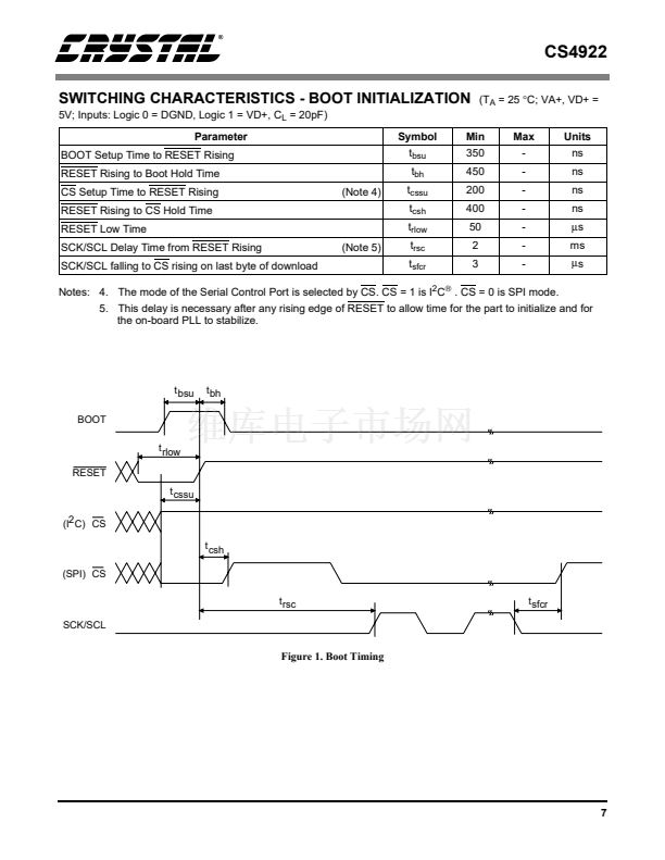
SWITCHING CHARACTERISTICS - BOOT INITIALIZATION
5V; Inputs: Logic 0 = DGND, Logic 1 = VD+, C
L
= 20pF)
Parameter
BOOT Setup Time to RESET Rising
RESET Rising to Boot Hold Time
CS Setup Time to RESET Rising
RESET Rising to CS Hold Time
RESET Low Time
SCK/SCL Delay Time from RESET Rising
SCK/SCL falling to CS rising on last byte of download
(Note 5)
(Note 4)
Symbol
t
bsu
t
bh
t
cssu
t
csh
t
rlow
t
rsc
t
sfcr
Min
350
450
200
400
50
2
3
Max
-
-
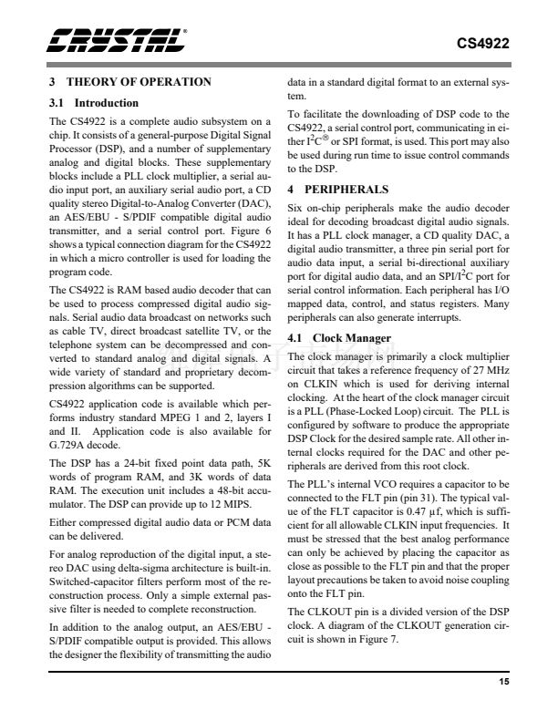
-
-
-
-
-
Units
ns
ns
ns
ns
碌s
ms
碌s
(T
A
= 25
擄C;
VA+, VD+ =
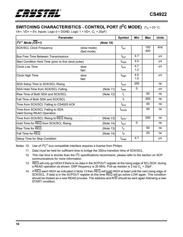
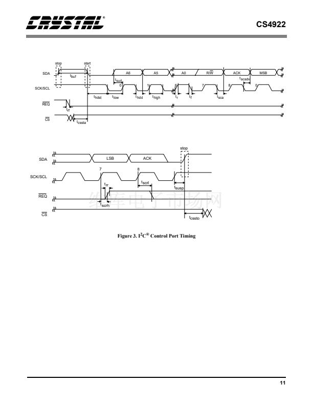
Notes: 4. The mode of the Serial Control Port is selected by CS. CS = 1 is I
2
C
廬
. CS = 0 is SPI mode.
5. This delay is necessary after any rising edge of RESET to allow time for the part to initialize and for
the on-board PLL to stabilize.
t bsu
BOOT
t bh
t rlow
RESET
t cssu
(I2 C) CS
t
csh
(SPI) CS
t rsc
SCK/SCL
t sfcr
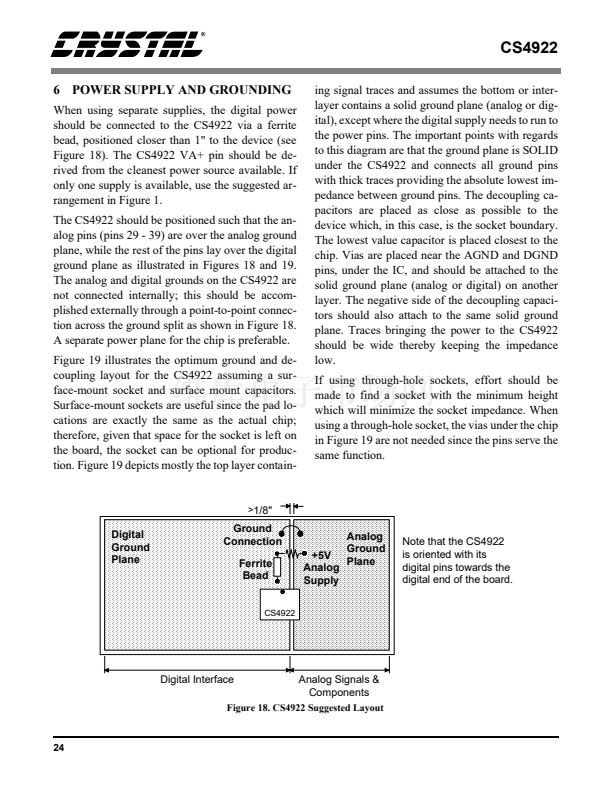
Figure 1. Boot Timing
7


 1
1
 2
2
 3
3
 4
4
 5
5
 6
6
 7
7
 8
8
 9
9
 10
10
 11
11
 12
12
 13
13
 14
14
 15
15
 16
16
 17
17
 18
18
 19
19
 20
20
 21
21
 22
22
 23
23
 24
24
 25
25
 26
26
 27
27
 28
28
 29
29
 30
30
 31
31
 32
32
 33
33
 34
34
