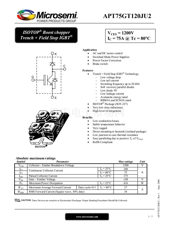
APT75GT120JU2
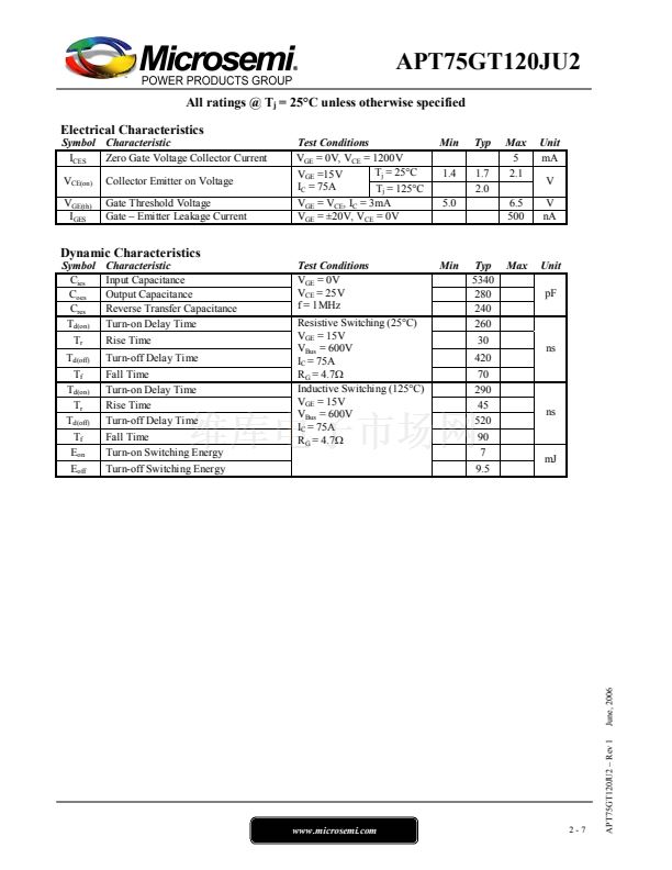
All ratings @ T
j
= 25擄C unless otherwise specified
Electrical Characteristics
Symbol Characteristic
I
CES
Zero Gate Voltage Collector Current
V
CE(on)
V
GE(th)
I
GES
Collector Emitter on Voltage
Gate Threshold Voltage
Gate 鈥?Emitter Leakage Current
Test Conditions
V
GE
= 0V, V
CE
= 1200V
T
j
= 25擄C
V
GE
=15V
I
C
= 75A
T
j
= 125擄C
V
GE
= V
CE
, I
C
= 3mA
V
GE
= 鹵20V, V
CE
= 0V
Min
1.4
5.0
Typ
1.7
2.0
Max
5
2.1
6.5
500
Unit
mA
V
V
nA
Dynamic Characteristics
Symbol
C
ies
C
oes
C
res
T
d(on)
T
r
T
d(off)
T
f
T
d(on)
T
r
T
d(off)
T
f
E
on
E
off
Characteristic
Input Capacitance
Output Capacitance
Reverse Transfer Capacitance
Turn-on Delay Time
Rise Time
Turn-off Delay Time
Fall Time
Turn-on Delay Time
Rise Time
Turn-off Delay Time
Fall Time
Turn-on Switching Energy
Turn-off Switching Energy
Test Conditions
V
GE
= 0V
V
CE
= 25V
f = 1MHz
Resistive Switching (25擄C)
V
GE
= 15V
V
Bus
= 600V
I
C
= 75A
R
G
= 4.7鈩?/div>
Inductive Switching (125擄C)
V
GE
= 15V
V
Bus
= 600V
I
C
= 75A
R
G
= 4.7鈩?/div>
Min
Typ
5340
280
240
260
30
420
70
290
45
520
90
7
9.5
Max
Unit
pF
ns
ns
mJ
www.microsemi.com
2-7
APT75GT120JU2 鈥?Rev 1
June, 2006


 1
1
 2
2
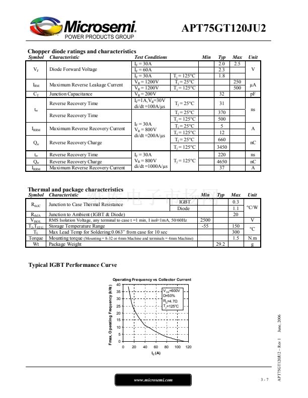 3
3
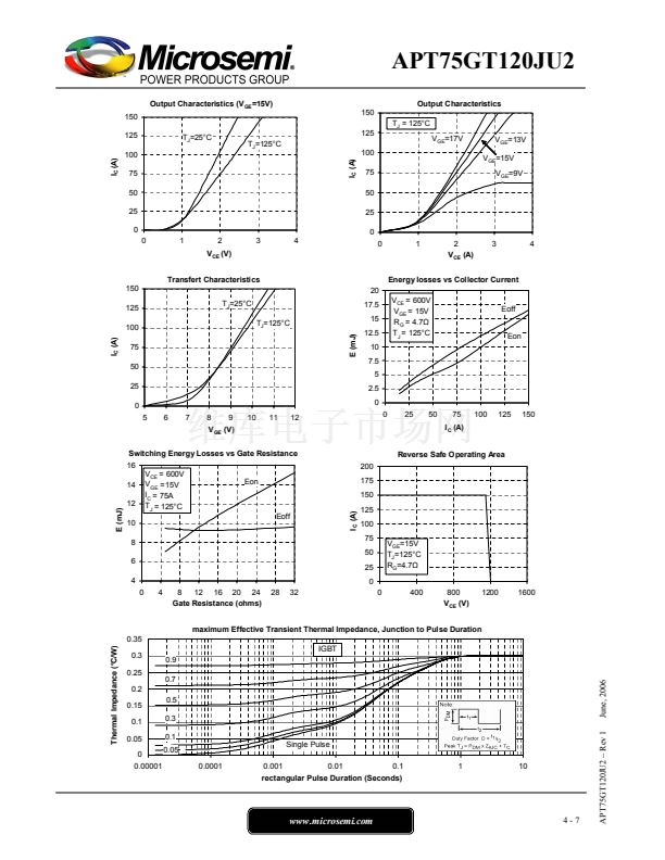 4
4
 5
5
 6
6
 7
7
