-
-

- 手機(jī)版
-

- 芯視頻 APP
-

- 微信公眾號(hào)
-

- 維庫官方抖音
-

- 微信頭條號(hào)
-
- |
-
- |
- |
- |

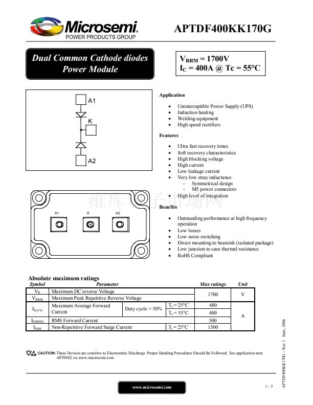
APTDF400KK170G
Dual Common Cathode diodes Power Module
210.00KB
MICROSEMI
掃碼查看芯片數(shù)據(jù)手冊(cè)
上傳產(chǎn)品規(guī)格書
1
半導(dǎo)體模塊
二極管,整流器
-
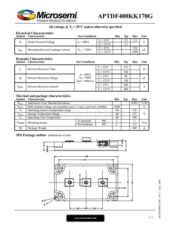
2.5V @ 400A
750µA @ 1700V
480A
1700V(1.7kV)
572ns
標(biāo)準(zhǔn)
標(biāo)準(zhǔn)恢復(fù) >500ns,> 200mA(Io)
1 對(duì)共陰極
底座安裝
LP4
SP6
散裝


聯(lián)系人:
聯(lián)系方式:

 1
1
 2
2
 3
3
