AD74111
there will be a fixed relationship between the instruction cycle
time of the DSP program and the AD74111, so a timer could be
used to accurately control the DAC updates. If a timer is not
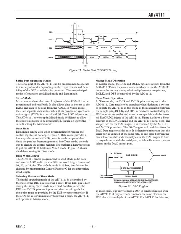
available, the Multiframe-Sync (MFS) mode could be used to
generate a DFS pulse every 16 or 32 DCLKs, allowing the DSP
to accurately control the number of DCLKs between updates
using an autobuffering or DMA type technique. In all cases for
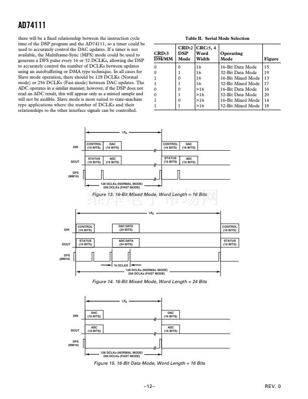
Slave mode operation, there should be 128 DCLKs (Normal
mode) or 256 DCLKs (Fast mode) between DAC updates. The
ADC operates in a similar manner; however, if the DSP does not
read an ADC result, this will appear only as a missed sample and
will not be audible. Slave mode is most suited to state-machine
type applications where the number of DCLKs and their
relationships to the other interface signals can be controlled.
Table II. Serial Mode Selection
CRD:3
DM/MM
0
0
1
1
0
0
1
1
CRD:2 CRC:5, 4
DSP
Word
Operating
Mode Width
Mode
0
1
0
1
0
1
0
1
16
16
16
16
>16
>16
>16
>16
16-Bit Data Mode
32-Bit Data Mode
16-Bit Mixed Mode
32-Bit Mixed Mode
16-Bit Data Mode
32-Bit Data Mode
16-Bit Mixed Mode
32-Bit Mixed Mode
Figure
15
19
13
17
16
20
14
18
1/
f
S
DIN
CONTROL
(16 BITS)
DAC
(16 BITS)
CONTROL
(16 BITS)
DAC
(16 BITS)
DOUT
STATUS
STATUS
(16 BITS)
ADC
(16 BITS)
STATUS
STATUS
(16 BITS)
(16 BITS)
ADC
(16 BITS)
DFS
(MM16)
128 DCLKs (NORMAL MODE)
256 DCLKs (FAST MODE)
Figure 13. 16-Bit Mixed Mode, Word Length = 16 Bits
1/
f
S
DIN
CONTROL
(16 BITS)
DAC DATA
(24 BITS)
CONTROL
(16 BITS)
DOUT
STATUS
(16 BITS)
ADC DATA
(24 BITS)
STATUS
(16 BITS)
DFS
(MM16)
16 DCLKS
128 DCLKs (NORMAL MODE)
256 DCLKs (FAST MODE)
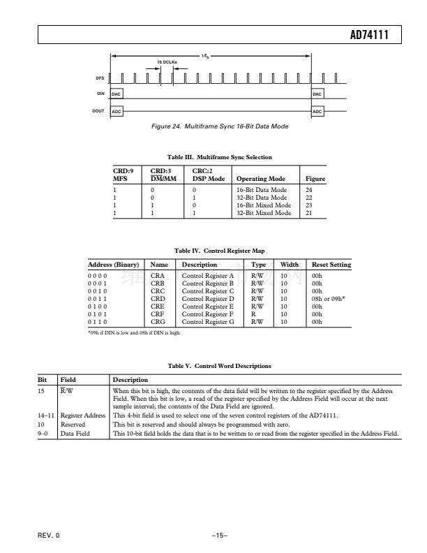
Figure 14. 16-Bit Mixed Mode, Word Length = 24 Bits
1/
f
S
DIN
DAC
(16 BITS)
DAC
(16 BITS)
DOUT
ADC
STATUS
(16 BITS)
ADC
STATUS
(16 BITS)
(16 BITS)
DFS
(MM16)
128 DCLKs (NORMAL MODE)
256 DCLKs (FAST MODE)
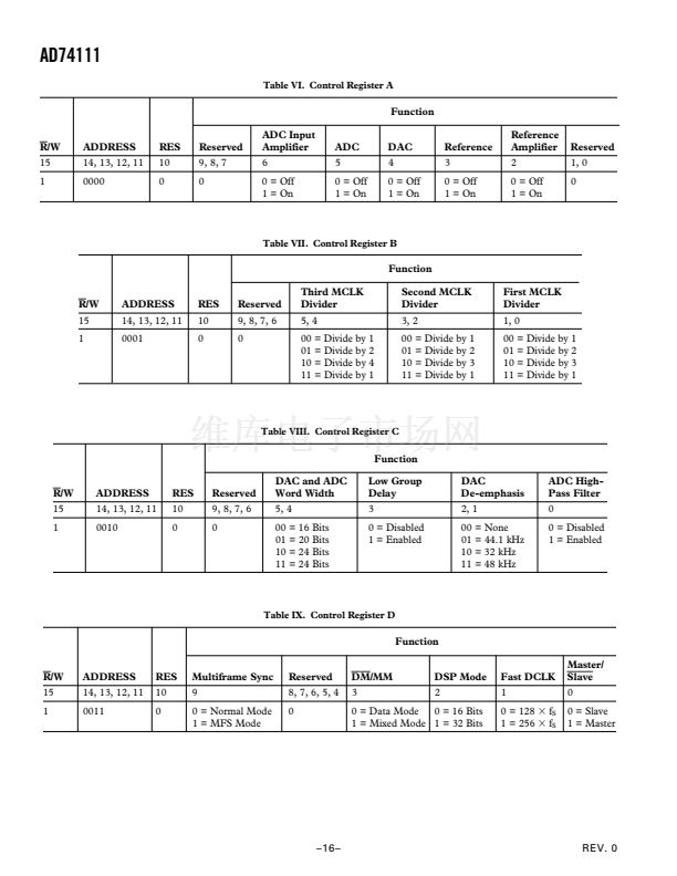
Figure 15. 16-Bit Data Mode, Word Length = 16 Bits
prev
next


 1
1
 2
2
 3
3
 4
4
 5
5
 6
6
 7
7
 8
8
 9
9
 10
10
 11
11
 12
12
 13
13
 14
14
 15
15
 16
16
 17
17
 18
18
 19
19
 20
20
