AD7142
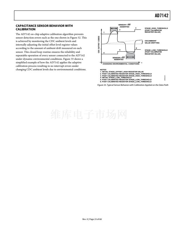
GPIO INT OUTPUT CONTROL
The INT output signal can be controlled by the GPIO pin when
the GPIO is configured as an input. The GPIO is configured as
an input by setting the GPIO_SETUP bits in the interrupt
configuration register to 01. See the GPIO section for more
information on how to configure the GPIO.
Enable the GPIO interrupt by setting the GPIO_INT_EN bit in
Register 0x007 to 1, or disable the GPIO interrupt by clearing this
bit to 0. The GPIO status bit in the conversion complete interrupt
status register reflects the status of the GPIO interrupt. This bit is
set to 1 when the GPIO has triggered INT. The bit is cleared on
readback from the register, provided the condition that caused
the interrupt has gone away.
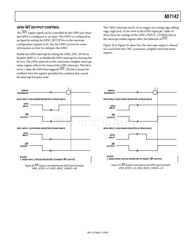
The GPIO interrupt can be set to trigger on a rising edge, falling
edge, high level, or low level at the GPIO input pin. Table 14
shows how the settings of the GPIO_INPUT_CONFIG bits in
the interrupt enable register affect the behavior of INT.
Figure 38 to Figure 41 show how the interrupt output is cleared
on a read from the CDC conversion complete interrupt status
register.
1
SERIAL
READBACK
GPIO INPUT HIGH WHEN REGISTER IS READ BACK
GPIO
INPUT
SERIAL
READBACK
GPIO INPUT HIGH WHEN REGISTER IS READ BACK
GPIO
INPUT
INT
OUTPUT
1
INT
OUTPUT
GPIO INPUT LOW WHEN REGISTER IS READ BACK
GPIO
INPUT
GPIO INPUT LOW WHEN REGISTER IS READ BACK
GPIO
INPUT
INT
OUTPUT
INT
OUTPUT
05702-028
Figure 38. INT Output Controlled by the GPIO Input Example,
GPIO_SETUP = 01, GPIO_INPUT_CONFIG = 00
Figure 39. INT Output Controlled by the GPIO Input Example,
GPIO_SETUP = 01, GPIO_INPUT_CONFIG = 01
Rev. 0 | Page 27 of 68
05702-029
NOTES
1. READ GPIO_STATUS REGISTER TO RESET INT OUTPUT.
NOTES
1. READ GPIO_STATUS REGISTER TO RESET INT OUTPUT.


 1
1
 2
2
 3
3
 4
4
 5
5
 6
6
 7
7
 8
8
 9
9
 10
10
 11
11
 12
12
 13
13
 14
14
 15
15
 16
16
 17
17
 18
18
 19
19
 20
20
 21
21
 22
22
 23
23
 24
24
 25
25
 26
26
 27
27
 28
28
 29
29
 30
30
 31
31
 32
32
 33
33
 34
34
 35
35
 36
36
 37
37
 38
38
 39
39
 40
40
 41
41
 42
42
 43
43
 44
44
 45
45
 46
46
 47
47
 48
48
 49
49
 50
50
 51
51
 52
52
 53
53
 54
54
 55
55
 56
56
 57
57
 58
58
 59
59
 60
60
 61
61
 62
62
 63
63
 64
64
 65
65
 66
66
 67
67
 68
68
