output voltage droop desired as a function of load current.
must be left open. Simply select a value for R
鈥?/div>
0.8V
(EQ. 1)
ATX supplies control the rise times of the individual voltage
outputs and insure proper sequencing.
Soft-Start Interval
Before a soft-start cycle is initiated, the controller holds the
active channel PWM drive signals in three-state as long as
the FS/EN pin is held at ground or the voltage applied to
VCC remains below the POR rising threshold.
Once VCC rises above the POR rising threshold and the
FS/EN pin is released from ground, a soft-start interval is
initiated. PWM operation begins and the resulting slow
ramp-up of output voltage avoids hitting an overcurrent trip
by slowly charging the discharged output capacitors. The
soft-start interval ends when the PGOOD signal transitions
to indicate the output voltage is within specification.
The soft-start interval is digitally controlled by the selection
of switching frequency. The maximum soft-start interval,
SS
Interval
, can be estimated for a given application:
2048
-
SS
Interval
= ------------
F
SW
(EQ. 4)
In applications where droop compensation is desired, tie the
DROOP and FB pins together. Select R
FB
first given the
following equation, where V
DROOP
is the desired amount of
output voltage droop at full load. This equation is contingent
upon the correct selection of the ISEN resistors discussed in
the
Fault Protection
section.
V
DROOP
3
-
R
FB
= ------------------------ = 20
脳10
xV
DROOP
50碌A(chǔ)
(EQ. 2)
Calculate R
OS
based on R
FB
using the following equation.
Where V
OUT,NL
is the desired output voltage under no-load
conditions.
0.8V
-
R
OS
=
R
FB
x
-------------------------------------------
V
OUT
,
NL
鈥?/div>
0.8V
(EQ. 3)
where F
SW
is the channel switching frequency.
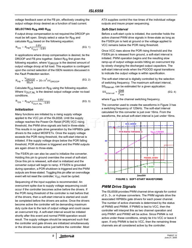
The converter used to create the waveforms in Figure 3 has
a switching frequency of 125kHz. The soft-start interval
calculated for this converter is just over 16ms. From the
waveforms, the actual soft-start interval is just under 16ms.
VCC, 2V/DIV
Initialization
Many functions are initiated by a rising supply voltage
applied to the VCC pin of the ISL6558. Until the supply
voltage reaches the Power-On Reset (POR) VCC rising
threshold, the PWM drive signals are held in three-state.
This results in no gate drive generation by the HIP660x gate
drivers to the output MOSFETs. Once the supply voltage
exceeds the POR rising threshold, the soft-start interval is
initiated. If the supply voltage drops below the POR falling
threshold, POR shutdown is triggered and the PWM outputs
are again driven to three-state.
The FS/EN pin can also be used to initialize the converter.
Holding this pin to ground overrides the onset of soft-start.
Once this pin is released, soft-start is initialized and the
converter output will begin to ramp. If FS/EN is grounded
during operation, a POR shutdown is triggered and the PWM
outputs are three-stated. Toggling this pin after an overvoltage
event will not reset the controller; V
CC
must be cycled.
Sequencing of the input supplies is recommended. An
overcurrent spike due to supply voltage sequencing could
occur if the controller becomes active before the drivers. If
the POR rising threshold of the controller is met before that
of the drivers, then a soft-start interval is started and could
be completed before the drivers are active. Once the drivers
become active the controller will be demanding maximum
duty cycle due to the lack of output voltage and could cause
an overcurrent trip. A soft-start interval would be initiated
shortly after this event and normal PWM operation would
result. The supply voltages should be sequenced such that
the controller and gate drivers are initialized simultaneously
or the drivers become active just before the controller. Most
9
POR RISING THRESHOLD
V
OUT
, 0.5V/DIV
0V
0V
PGOOD, 2V/DIV
0V
FB, 0.5V/DIV
0V
2ms/DIV
FIGURE 3. SOFT-START WAVEFORMS
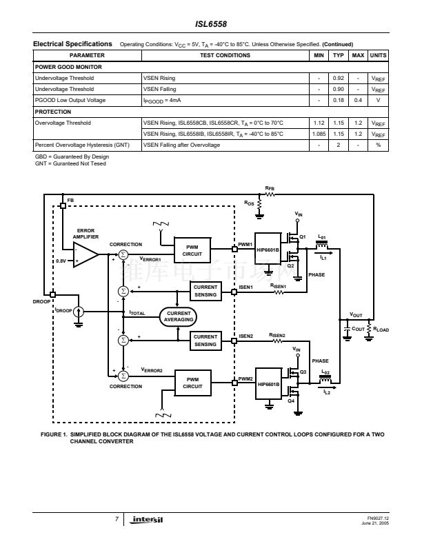
PWM Drive Signals
The ISL6558 provides PWM channel drive signals for control
of 2-, 3-, or 4-phase converters. The PWM signals drive the
associated HIP660x gate drivers for each power channel.
The number of active channels is determined by the status
of PWM3 and PWM4. If PWM3 is tied to VCC, then the
controller will interpret this as two channel operation and
only PWM1 and PWM2 will be active. Since PWM4 is not
active under these conditions, simply tie it to VCC or leave it
open. If only PWM4 is tied to VCC, then the remaining three
channels are all considered active by the controller.
FN9027.12
June 21, 2005


 1
1
 2
2
 3
3
 4
4
 5
5
 6
6
 7
7
 8
8
 9
9
 10
10
 11
11
 12
12
 13
13
 14
14
 15
15
 16
16
