ISL6558
Absolute Maximum Ratings
Supply Voltage, VCC . . . . . . . . . . . . . . . . . . . . . . . . . . . . . . . . . .+7V
Input, Output, or I/O Voltage . . . . . . . . . . . GND -0.3V to V
CC
+0.3V
ESD Classification
Human Body Model . . . . . . . . . . . . . . . . . . . . . . . . . . . . . . . . .3kV
Machine Model . . . . . . . . . . . . . . . . . . . . . . . . . . . . . . . . . . . .250V
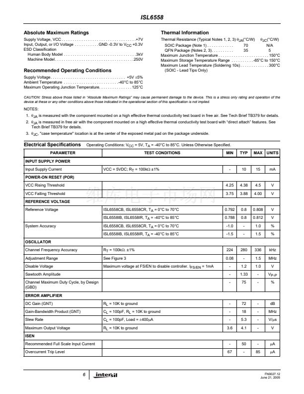
Thermal Information
Thermal Resistance (Typical Notes 1, 2, 3)
胃
JA
(擄C/W)
胃
JC
(擄C/W)
SOIC Package (Note 1) . . . . . . . . . . . .
70
N/A
QFN Package (Notes 2, 3). . . . . . . . . .
35
5
Maximum Junction Temperature . . . . . . . . . . . . . . . . . . . . . . . 150擄C
Maximum Storage Temperature Range . . . . . . . . . . -65擄C to 150擄C
Maximum Lead Temperature (Soldering 10s) . . . . . . . . . . . . . 300擄C
(SOIC - Lead Tips Only)
Recommended Operating Conditions
Supply Voltage. . . . . . . . . . . . . . . . . . . . . . . . . . . . . . . . . . +5V
鹵5%
Ambient Temperature . . . . . . . . . . . . . . . . . . . . . . . . .-40擄C to 85擄C
Maximum Operating Junction Temperature. . . . . . . . . . . . . . . 125擄C
CAUTION: Stress above those listed in 鈥淎bsolute Maximum Ratings鈥?may cause permanent damage to the device. This is a stress only rating and operation of the
device at these or any other conditions above those indicated in the operational section of this specification is not implied.
NOTES:
1.
胃
JA
is measured with the component mounted on a high effective thermal conductivity test board in free air. See Tech Brief TB379 for details.
2.
胃
JA
is measured in free air with the component mounted on a high effective thermal conductivity test board with 鈥渄irect attach鈥?features. See
Tech Brief TB379 for details.
3.
胃
JC
, "case temperature" location is at the center of the exposed metal pad on the package underside.
Electrical Specifications
PARAMETER
INPUT SUPPLY POWER
Input Supply Current
POWER-ON RESET (POR)
VCC Rising Threshold
VCC Falling Threshold
REFERENCE VOLTAGE
Reference Voltage
Operating Conditions: V
CC
= 5V, T
A
= -40擄C to 85擄C. Unless Otherwise Specified.
TEST CONDITIONS
MIN
TYP
MAX
UNITS
VCC = 5VDC; R
T
= 100k鈩?鹵1%
-
10
15
mA
4.25
3.75
4.38
3.88
4.5
4.00
V
V
ISL6558CB, ISL6558CR, T
A
= 0擄C to 70擄C
ISL6558IB, ISL6558IR, T
A
= -40擄C to 85擄C
0.792
0.788
-1.0
-1.5
0.8
0.8
-
-
0.808
0.812
1.0
1.5
V
V
%
%
System Accuracy
ISL6558CB, ISL6558CR, T
A
= 0擄C to 70擄C
ISL6558IB, ISL6558IR, T
A
= -40擄C to 85擄C
OSCILLATOR
Channel Frequency Accuracy
Adjustment Range
Disable Voltage
Sawtooth Amplitude
Channel Maximum Duty Cycle, by Design
(GBD)
ERROR AMPLIFIER
DC Gain (GNT)
Gain-Bandwidth Product (GNT)
Slew Rate
Maximum Output Voltage
ISEN
Recommended Full Scale Input Current
Overcurrent Trip Level
-
67
50
-
-
85
碌A(chǔ)
碌A(chǔ)
R
L
= 10K to ground
C
L
= 100pF, R
L
= 10K to ground
C
L
= 100pF, Load =
鹵400碌A(chǔ)
R
L
= 10K to ground
-
-
-
3.6
72
18
5.3
4.1
-
-
-
-
dB
MHz
V/碌s
V
R
T
= 100k鈩? 鹵1%
See Figure 3
Maximum voltage at FS/EN to disable controller. I
FS/EN
= 1mA
224
0.08
-
-
-
280
-
1.2
1.33
75
336
1.5
1.0
-
-
kHz
MHz
V
V
P-P
%
6
FN9027.12
June 21, 2005


 1
1
 2
2
 3
3
 4
4
 5
5
 6
6
 7
7
 8
8
 9
9
 10
10
 11
11
 12
12
 13
13
 14
14
 15
15
 16
16
